Phase frequency detector

a phase frequency and detector technology, applied in the direction of pulse automatic control, pulse technique, instruments, etc., can solve the problems of reducing power consumption, reducing power consumption, and reducing the operation speed of the pfd, so as to achieve fast phase lock, low noise characteristics, and low power consumption

Inactive Publication Date: 2006-03-16
ELECTRONICS & TELECOMM RES INST
View PDF10 Cites 31 Cited by
  • Summary
  • Abstract
  • Description
  • Claims
  • Application Information

AI Technical Summary

Benefits of technology

[0014] The present invention is directed to a phase frequency detector capable of operating at a

Problems solved by technology

The charge pump connected to the output stage of the PFD requires more than a certain number of duration pulses for an exact switching operation so that the extremely small delay means is not allowed in the reset path.
Th

Method used


Image

  • Phase frequency detector
  • Phase frequency detector
  • Phase frequency detector

Examples


first embodiment

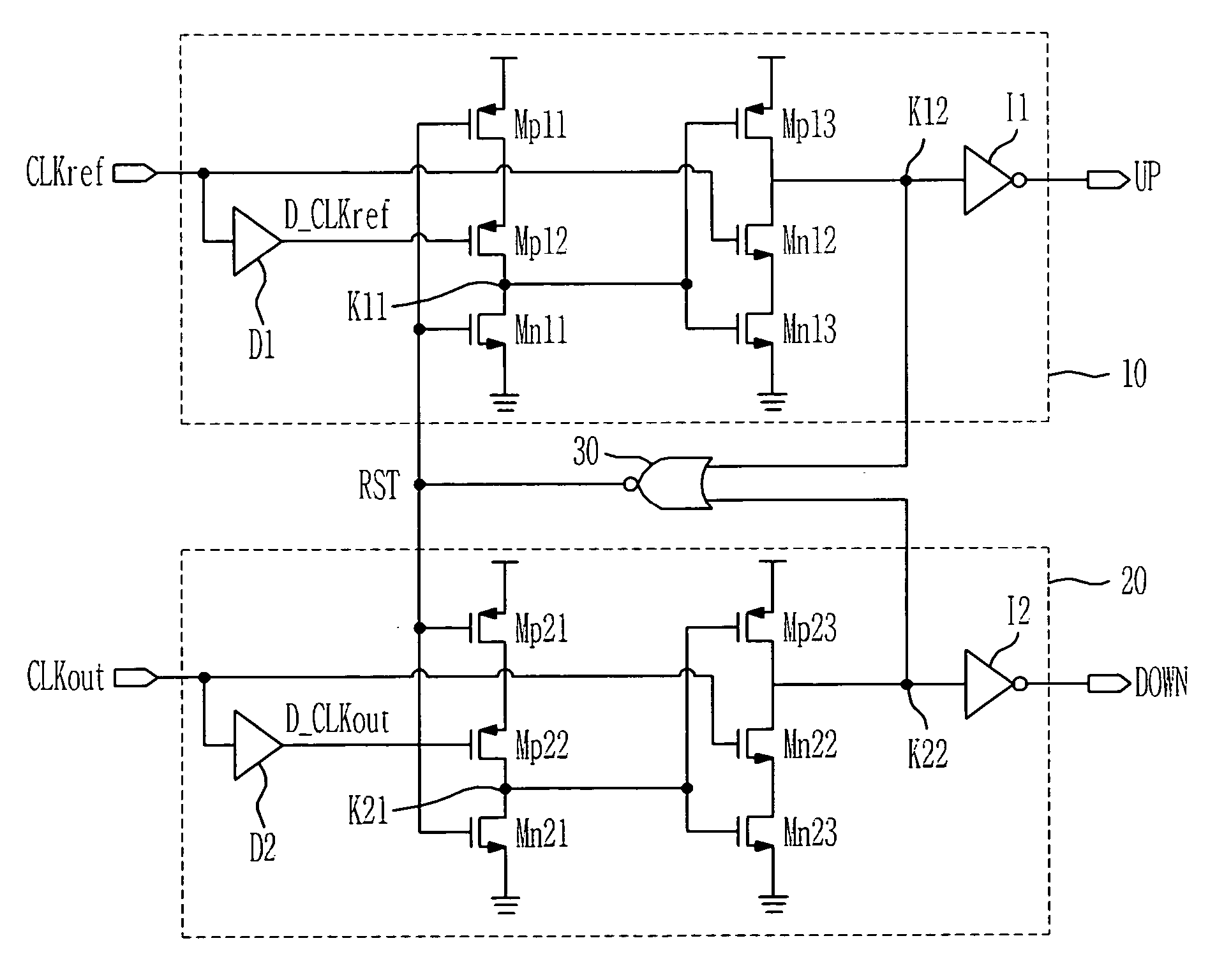
[0033]FIG. 6 is a circuit diagram for explaining a phase frequency detector according to the present invention.

[0034] The phase frequency detector (PFD) of the present invention includes: an UP signal output unit 10 for receiving a reference clock CLKref and a predetermined time delayed reference clock D_CLKref; a DOWN signal output unit 20 for receiving an outer clock CLKout and a predetermined time delayed outer clock D_CLKout; and a logical gate for logically combining outputs of the UP signal output unit 10 and the DOWN signal output unit 20 to generate a reset signal RST.

[0035] The UP signal output unit 10 includes: a first stage operated according to the predetermined time delayed reference clock D_CLKref, delayed by delay means D1, and the reset signal RST; a second stage operated according to the reference clock CLKref and an output of the first stage; and an inverter I1 for inverting an output of the second stage.

[0036] The first stage includes transistors Mp11 and Mp12 c...

second embodiment

[0052]FIG. 8 is a circuit diagram for explaining a phase frequency detector according to the present invention, where transistors Mn14 and Mn24 are added to the phase frequency detector of FIG. 6.

[0053] The transistor Mn14 connected between the output node K12 and a node K13 receives the delayed reference clock D_CLKref through a gate, and the transistor Mn24 connected between the output node K22 and a node K23 receives the delayed outer clock D_CLKout through a gate.

[0054] The PFD according to the present embodiment has the same operation characteristic as that of FIG. 5, and the cutoff frequency becomes td5*fclk*2π<π, which is different from that for the PFD of FIG. 6. Therefore, the cutoff frequency is twice higher than that for the PFD of FIG. 6. This is the same cutoff frequency as that for the conventional PFD arranged as shown in FIG. 4.

[0055] The PFD according to the present invention has almost the same power consumption and noise characteristic as the PFD of FIG. 6, so t...


PUM


Abstract

Provided is a phase frequency detector for use in a phase locked loop (PLL) or a delay locked loop (DLL), the phase frequency detector including: an UP signal output unit having a first stage operated according to a reference clock delayed by a predetermined time and a reset signal, a second stage operated according to the reference clock and an output of the first stage, and an inverter for inverting an output of the second stage; a DOWN signal output unit having: a first stage operated according to an outer clock delayed by a predetermined time and the reset signal, a second stage operated according to the outer clock and an output of the first stage, and an inverter for inverting an output of the second stage; and a logic gate logically combining the output of the second stage of the UP signal output unit and the output of the second stage of the DOWN signal output unit to generate the reset signal, thereby a phase range of the input signal with which an effective control signal can be obtained is wide so that low power consumption and low noise characteristics can be obtained due to fast phase lock, low power consumption of a dynamic logic, and fast signal transmission.

Description

CROSS-REFERENCE TO RELATED APPLICATION [0001] This application claims priority to and the benefit of Korean Patent Application No. 2004-90672, filed on Nov. 9, 2004, the disclosure of which is incorporated herein by reference in its entirety. BACKGROUND [0002] 1. Field of the Invention [0003] The present invention relates to a phase frequency detector for use in a phase locked loop (PLL) or a delay locked loop (DLL) and, more specifically, to a phase frequency detector capable of operating at a high frequency and having fast phase lock, low power consumption, and low noise characteristics. [0004] 2. Discussion of Related Art [0005] A phase locked loop (hereinafter, referred to as PLL), which is a frequency feedback circuit that generates any frequency according to a predetermined clock signal, is used for a frequency synthesizer and a data processor, etc. [0006] In general, the PLL includes a reference frequency generator, a voltage controlled oscillator (VCO), a frequency divider f...

Claims


Application Information

Patent Timeline
IPC IPC(8): H03K9/06
CPCH03L7/0891H03D13/004H03L7/085
Inventor TAK, GEUM-YOUNGHYUN, SEOK-BONGPARK, KYUNG-HWANKANG, TAE-YOUNGPARK, SEONG-SU
Owner ELECTRONICS & TELECOMM RES INST
Why Eureka
Try Eureka