
Acoustic wave guidance in a vehicle

Inactive Publication Date: 2006-03-16
DAIMLER AG
View PDF4 Cites 20 Cited by
  • Summary
  • Abstract
  • Description
  • Claims
  • Application Information

AI Technical Summary

Benefits of technology

[0007] It is an object of the invention to provide an acoustic apparatus which firstly has no large-volume hard components in the proximity of its sound emergence location and secondly has the best possible matching for the acoustic impedance between the air column produced by a sound transducer and the ambient air.
[0009] The object is achieved by virtue of the inventive refinement of an acoustic apparatus for producing audio signals, in which the sound transducer and at least one sound emergence location are physically separate from one another. Such apparatuses have an air-guiding sound line which is connected to the sound emergence location and where a means is provided for achieving acoustic impedance matching for the air in the sound line and the ambient air in order to reduce resonance effects. In this case, the means for acoustic resonance matching is made of a material which has the acoustic impedance of air. In inventive fashion, this material is now placed in two dimensions and conclusively over the at least one sound emergence opening. This advantageously achieves acoustic impedance matching which not only requires the smallest possible physical space but also provides protection from the entry of dirt into the apparatus at the same time.
[0010] In particularly advantageous fashion, the material which has the acoustic impedance of air is made of a fibrous and / or porous material, particularly felt, sponge material, unwoven fabric or felt metal. Since the acoustic impedance of air is 41.4 rayl, the material used to terminate the sound line should likewise have a rayl value in this order of magnitude. Commercially, materials called felt metal, for example, which have corresponding rayl values can be obtained without difficulty. The sealing of the end of the tube with material which has a value of approximately 40 rayl simulates a tube of infinite length and thus results in ideal resonance-free emergence of sound. In particularly advantageous fashion, the thickness of the felt metal used should be in the order of magnitude of 1 mm, so that there is firstly adequate shock and compression resistance and secondly the lowest possible damping of the sound waves which are to be transmitted.

Problems solved by technology

Normally, however, commercial appliances today allow only coarse balancing of the volume between “right” and “left” and between “front” and “back”.
Finer volume adjustment for each seat is not possible.
A drawback of these arrangements in which the acoustic system's loudspeaker is directly in the headrest is the reduced accident safety, in particular, since relatively large hard objects are integrated in the otherwise soft headrest and could result in head injuries.
In addition, integrating relatively large-volume loudspeakers greatly restricts the visual design options for the headrest.

Method used


Image

  • Acoustic wave guidance in a vehicle
  • Acoustic wave guidance in a vehicle
  • Acoustic wave guidance in a vehicle

Examples


Embodiment Construction

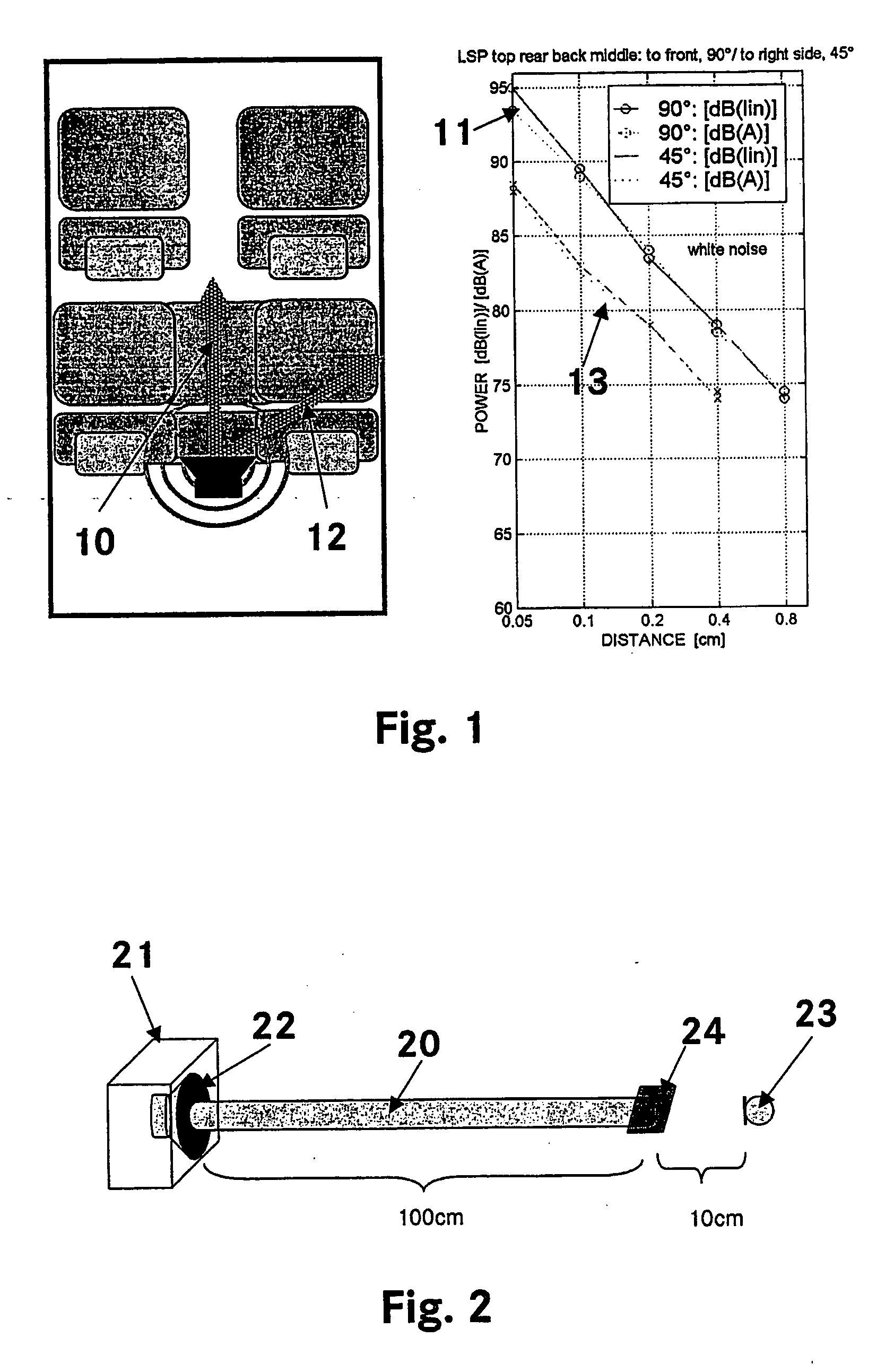
[0023]FIG. 1a) schematically shows the interior of a motor vehicle with two individual seats, driver and front passenger seats, and a bench seat in the back. Within such a typical vehicle interior, the dissemination of the from a loudspeaker signal radiated in the center above the bench seat's back rest has been measured. FIG. 1b) shows the power drop in the loudspeaker signal as a function of distance. In this context, curve 11 shows the power drop in the direction 10 of the driver and of the front passenger seat and curve 13 shows the power drop in the direction 12 of the passengers on the back seat at an angle of 45° from the loudspeaker. It can clearly be seen that the sound power drops by 6 dB whenever the distance is doubled. This applies to the unweighted level and to the A weighting (the A weighting takes into account the subjective hearing sensitivity in a coarse approximation). The 6 dB value is the correct value if we are in the direct sound field of the sources. This con...


PUM


Abstract

The aim of the invention is to ensure the same high quality of acoustic radiation from audio systems on each seat of current vehicles. Said aim is achieved by a novel acoustic device for generating audio signals, which allows sound sources to be integrated into the area located near the headrest of a vehicle seat such that the volume can be regulated in an individual manner without unduly disturbing the other passengers in a vehicle, who hear the audio signals to a significantly reduced extent. The headrest does not comprise any loudspeakers, thus offering good creative possibilities regarding accident protection and design. The acoustic near field at the headrest is generated by means of a sound line. The loudspeaker is disposed inside the backrest or under the seat, for example, while the sound line terminates in the headrest. Tuned pipes, the end of which is adjusted to the acoustic impedance of the clearance zone, are used as a sound line.

Description

BACKGROUND OF THE INVENTION [0001] 1. Field of the Invention [0002] The invention relates to an acoustic apparatus for producing audio signals in accordance with the features of the precharacterizing part of patent claim 1. [0003] 2. Related Art of the Invention [0004] Audio diffusion in vehicles today is intended to ensure the same level of quality in every seat. The aim is for all occupants to hear virtually the same audio signal at the same quality and at the same volume; in complex systems, this includes with a stereo or surround effect. Normally, however, commercial appliances today allow only coarse balancing of the volume between “right” and “left” and between “front” and “back”. Finer volume adjustment for each seat is not possible. Techniques are known which are aimed at separating the audio output so that people who are physically next to one another can be provided with quite different audio programs. Thus, by way of example, WO 01 / 08449 A1 describes a method for reproduc...

Claims


Application Information

Patent Timeline
IPC IPC(8): H04R1/02H04R1/28H04R1/30
CPCG01N2291/02491H04R2499/13H04R1/023B60N2/879
Inventor HOFMANN, MARCUSLINHARD, KLAUS
Owner DAIMLER AG
Learn More