Centrifugally-cast tube and related method and apparatus for making same

a centrifugally cast tube and tube body technology, applied in the direction of hydrocarbon oil treatment, gear teeth, rectilinear broach, etc., can solve the problems of not providing adequate deformation and/or orientation of the subsurface or material lattice of the inner surface of the tube, electropolished surface is not resistant to corrosion, carburization or metal dusting, etc., to achieve superior surface roughness and dimensional accuracy of the interior surface.

Inactive Publication Date: 2006-03-16
DEMAREST JOEL +1
View PDF8 Cites 10 Cited by
  • Summary
  • Abstract
  • Description
  • Claims
  • Application Information

AI Technical Summary

Benefits of technology

[0009] In one aspect, the present invention may be a centrifugally-cast tube comprising: a tubular body made from a creep-resistant alloy, the body having an exterior surface and an interior surface, the interior surface including a plurality of bosses and a plurality of grooves, and the plurality of bosses and grooves being mechanically machined into the interior surface. Another feature of this aspect of the invention may be that the plurality of bosses and grooves are defined by a plurality of intersecting concave and convex radii. Another feature of this aspect of the invention may be that the plurality of bosses and grooves are formed by a broaching process. Another feature of this aspect of the invention may be that the interior surface is resistant to carburization and metal dusting. Another feature of this aspect of the invention may be that the surface roughness and dimensional accuracy of the interior surface is superior to that of a centrifugally-cast tube wherein the plurality of bosses and grooves are formed by a electrochemical machining process. Another feature of this aspect of the invention may be that the plurality of bosses and grooves form a profile that is at least 5% longer than a circumference of a smallest circle that encompasses the entire resulting profile. Another feature of this aspect of the invention may be that the interior surface has a surface roughness of less than 125 RMS (CLA).
[0010] In another aspect, the present invention may include a method of improving a centrifugally-cast tube comprising: passing a first cutting tool having a plurality of first cutting inserts through a bore of the tube so as to mechanically remove a first quantity of material from the bore and to commence the formation of a plurality of grooves and bosses; passing a second cutting tool having at plurality of second cutting inserts through the bore so as to mechanically remove a second quantity of material from the bore and to continue the formation of the plurality of grooves and bosses, the plurality of second cutting inserts having dimensions different than corresponding dimensions of the plurality of first cutting inserts; and continuing to pass additional cutting tools having a plurality of additional cutting inserts through the bore so as to continue to mechanically remove additional quantities of material from the bore until a desired profile of grooves and bosses is achieved, each set of additional cutting tools having dimensions different than corresponding dimensions of the cutting inserts employed in the immediately preceding pa

Problems solved by technology

A key drawback to the tube disclosed in the '340 patent, however, is that it is not resistant to corrosion, carburization or metal dusting.
As is known in the art, use of the ECM method results in an electropolished surface and does not provide adequate deformation and/or orientation of the subsurface or material lattice of the inner surface of the tube.
In this regard, it is well known that an electropolished surface i

Method used


Image

  • Centrifugally-cast tube and related method and apparatus for making same
  • Centrifugally-cast tube and related method and apparatus for making same
  • Centrifugally-cast tube and related method and apparatus for making same

Examples


Embodiment Construction

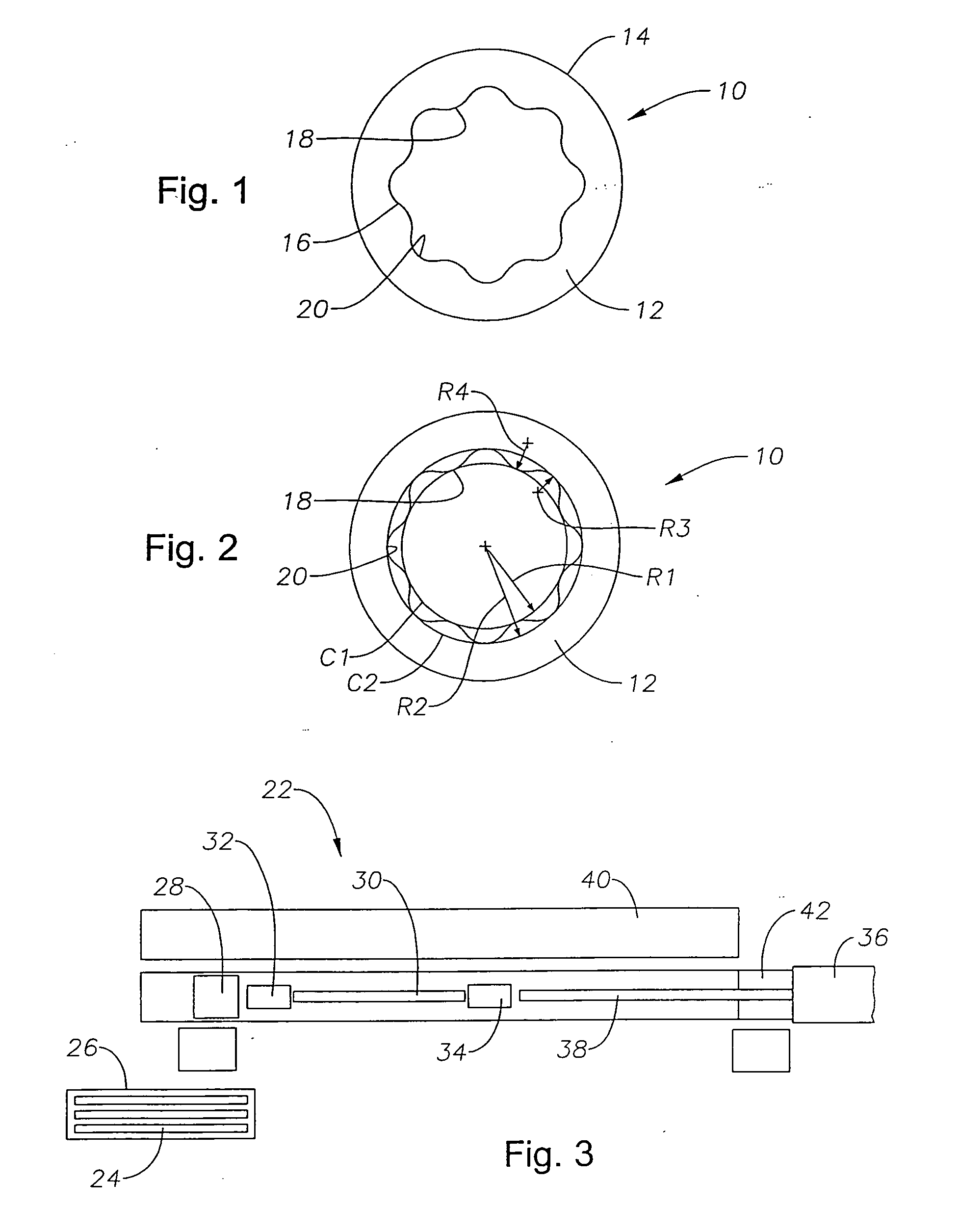
[0036] Referring to the drawings in detail, wherein like numerals denote identical elements throughout the several views, there is shown in FIG. 1 a specific embodiment of a centrifugally-cast tube 10 constructed in-accordance with the present invention. In a specific embodiment, the tube 10 may include a body 12 made from a creep-resistant alloy, such as, for example, Manaurite 36X. The body 12 may include an exterior surface 14 and an interior surface 16. The interior surface 16 may include a plurality of bosses 18 and a plurality of grooves 20 disposed therebetween. While the specific embodiment shown in FIG. 1 illustrates a tube 10 having eight bosses 18 and eight grooves 20, those numbers should not be taken as a limitation, but, instead, the present invention covers any number of bosses 18 and grooves 20. In a specific embodiment, as shown in FIG. 2, the peaks of the bosses 18 may intersect a circle C1 having a radius R1. In a specific embodiment, the radius R1 may be 19 milli...


PUM

PropertyMeasurementUnit
Lengthaaaaaaaaaa
Dimensionaaaaaaaaaa

Abstract

An improved centrifugally-cast tube is provided, along with a related method and apparatus of making the tube. The tube includes a plurality of grooves and bosses that are mechanically machined into an interior surface of the tube, such as by a broaching process. The profile of grooves and bosses may be defined by a plurality of intersecting concave and convex radii. The tube is resistant to creep, carburization and metal dusting. The tube also has an enhanced heat transfer rate, and a desirable surface roughness. A method of making the tube is also provided. The method essentially consists of mechanically deforming the interior surface of the tube by passing a series of cutting inserts on support rings having incrementally-differing dimensions over the interior surface. An apparatus is also provided which includes a telescoping shaft upon which is mounted at least one cutting tool that has a plurality of cutting inserts and is adapted to form a plurality of grooves and bosses in the interior surface of the tube. The grooves and bosses may be straight or spiraled.

Description

BACKGROUND OF THE INVENTION [0001] 1. Field Of The Invention [0002] The present invention relates to furnace equipment for use in petrochemical plants, and more particularly, to improved centrifugally-cast tubes for use in such equipment and to a method and apparatus of making such tubes. [0003] 2. Description Of The Related Art [0004] It is well known that there are two basic types of furnaces used in petrochemical plants, one being “steam cracker” furnaces, and the other being “steam reformer” furnaces. Steam cracker furnaces are mainly used to make ethylene, and steam reformer furnaces are mainly used to make hydrogen. Both types of furnaces include a number of tubes, generally arranged vertically, that form a continuous flow path, or coil, through the furnace. The flow path or coil includes an inlet and an outlet. In both types of furnaces, a mixture of a hydrocarbon feedstock and steam are fed into the inlet and passed through the tubes. The tubes are exposed to extreme heat ge...

Claims


Application Information

Patent Timeline
IPC IPC(8): B23D37/00B23F5/28B22D13/02B23D43/04C10G75/00F16L9/02F28F1/40
CPCB22D13/02Y10T409/503116B23D39/00B23D43/02B23D43/04B23P15/00F28D2021/0059F28F1/40Y10T407/1628Y10T409/40105Y10T409/4028Y10T409/40315Y10T409/400175Y10T428/12Y10T409/4077Y10T409/40175Y10T409/402975Y10T409/404375Y10T409/4063Y10T407/1671B23D37/04Y10T83/0304Y10T83/0311Y10T83/0524Y10T83/0596Y10T83/384F16L9/02
Inventor DEMAREST, JOELVERDIER, GILLES
Owner DEMAREST JOEL
Why Eureka
Try Eureka