Structual roof panel systems

a structure and roof panel technology, applied in the direction of roofs, transportation and packaging, vehicle arrangements, etc., can solve the problems of adding yet another burden to manufacturing problems, difficult manipulation of the area of headliner and overhead system components, and time-consuming and expensive parts of vehicle assembly

Inactive Publication Date: 2006-03-23
JOHNSON CONTROLS TECH CO
View PDF33 Cites 67 Cited by
  • Summary
  • Abstract
  • Description
  • Claims
  • Application Information

AI Technical Summary

Benefits of technology

[0041] A still further feature of the present invention is to allow for use of simple, non-structural, die-cut, stretched, or otherwise prepared materials for the headliners that are attached to the structural roof panel systems of the present invention.
[0042] A still further feature of t...

Problems solved by technology

The assembly of the headliner and overhead system components within the confines of the vehicle interior is a time consuming and expensive part of vehicle assembly.
For example, many components must be attached upwardly in the Z axis direction, and manipulation in that area is difficult using robotics or hand labor to complete mechanical attachments, as w...

Method used


Image

  • Structual roof panel systems
  • Structual roof panel systems
  • Structual roof panel systems

Examples


first embodiment

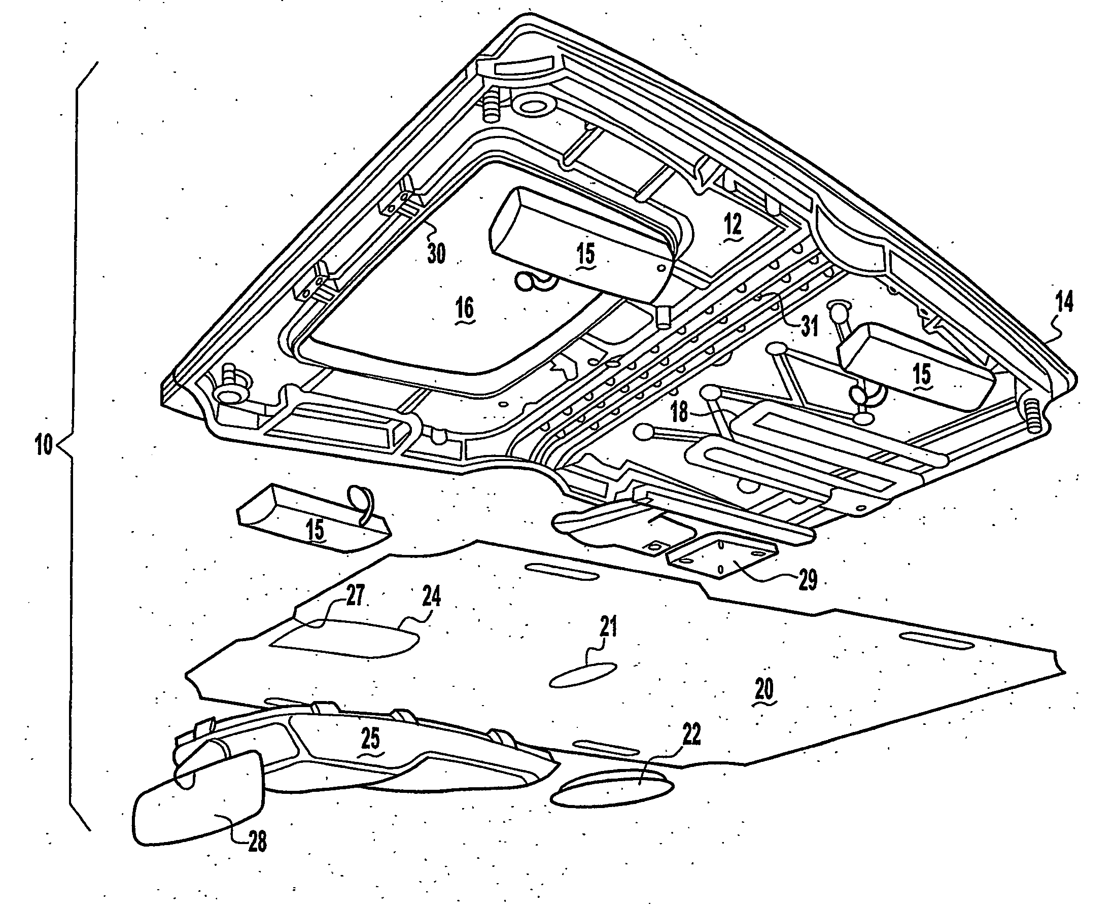
[0060] Proceeding now to the description of four embodiments of the invention, FIG. 1 shows an exploded view of an all-in-one structural roof panel system according to the The overall roof system is designated by the reference number 10, while the structural all-in-one engineered structural component is indicated at the reference numeral 12. As can be seen from FIG. 1, the roof panel 14 is formed with the structural component 12, and a sunroof or other “optional equipment” can be added by knocking out predetermined areas, such as 16. Various overhead system components are also illustrated in FIG. 1. They include side airbag modules 15, an antenna farm 18, a headliner 20, including an aperture 21 adapted to receive a dome light 22, and an aperture 24 adapted to receive an overhead console 25. An edge cut-out 27 is also included to accommodate rearview mirror 28. A motor for a sunroof is also illustrated 29. As has been clearly set forth above, the number and location for the various...

second embodiment

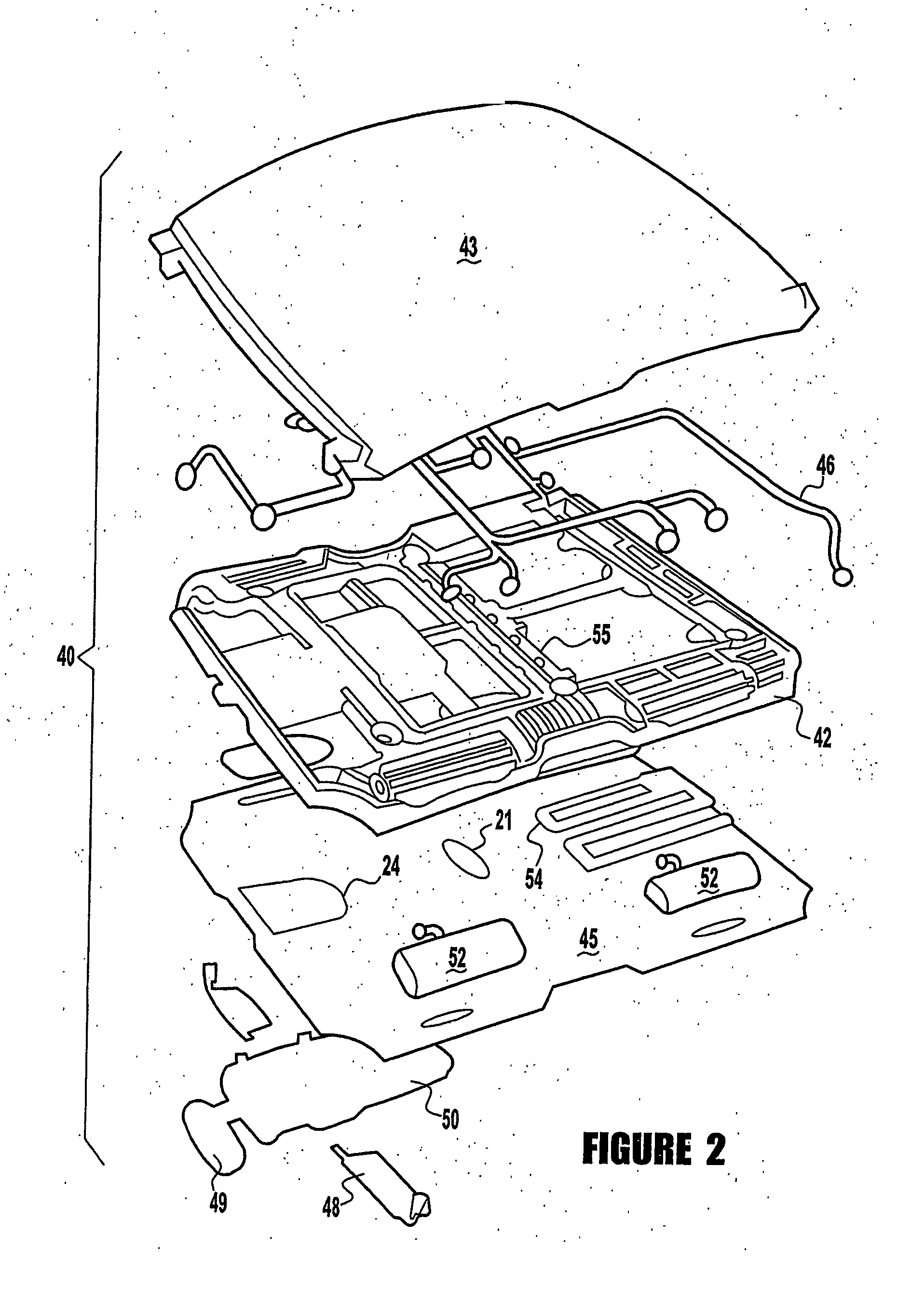
[0062] A second embodiment is depicted in FIG. 2, which includes a super-structure system 40 having a super-structure element 42, a roof panel 43, and a headliner 45. In this embodiment, roof panel 43 is added as a separate assembly set to the super-structure 42, along with other overhead components illustrated here, including wire harness 46, visors 48, a rearview mirror 49, an overhead console 50, airbag assemblies 52, and antenna grid 54.

[0063] The super-structure 42 is preferably made from a resin, which may be reinforced if desired. The super-structure 42 includes a network of supporting ribs 55, as well as other predesignated attachment areas for the listed overhead components, or other overhead components which may be selected by the dealer or customer. The joining of the overhead components, as well as the headliner 45 and roof panel 43, may be accomplished using any of the fastening techniques described above.

[0064] The third embodiment of the present invention is illustra...


PUM


Abstract

A structural roof panel system for a vehicle includes mounting areas molded in or readily attached to the structural element. In a first embodiment, the roof panel is replaced by an engineered, structural system to support overhead components, the headliner, etc. In a second embodiment, an internal super-structure is located between the roof panel and a nonstructural headliner, all overhead system components being readily attachable to the super-structure at pre-designed and designated locations. In a third embodiment, the structural components are moved to pods, and all overhead components are attached thereto. In each embodiment, the headliner becomes an aesthetic and acoustic cover only that does not require structural strength. Furthermore, in each embodiment, a single, integral roof system can be supplied to a vehicle manufacturer, including the exterior panel, structural support for overhead components, the overhead components attached thereto, and the headliner.

Description

[0001] This application claims priority to U.S. Provisional Patent Application 06 / 424,566 filed Nov. 7, 2002 and U.S. Provisional Patent Application 06 / 424,569 filed on Nov. 7, 2002.BACKGROUND OF THE INVENTION [0002] 1. Field of the Invention [0003] The present invention relates generally to roof systems for vehicles and more particularly to roof systems which include a structural element which include or support the exterior roof panel, and which support the headliner and a wide variety of systems commonly used in the overhead portion of vehicles, such as automobiles, vans, SUVs, trucks, and the like. In its preferred embodiments, the present invention relates more specifically to an all-in-one structural system in which the roof panel and the structural support are molded as a unitary body, a second embodiment in which a skeletal super-structure is designed to receive any of a wide variety of overhead components and the roof panel, and a third embodiment in which structural elemen...

Claims


Application Information

Patent Timeline
IPC IPC(8): B62D25/06B60R13/02B62D65/06
CPCB60R13/0225B62D65/06B62D25/06
Inventor STREBE, KEVINMFISCHER, DOUGLASANORLAND, LEIF ANDREW
Owner JOHNSON CONTROLS TECH CO
Why Eureka
Try Eureka