High power, long focus electron source for beam processing

a beam processing and electron source technology, applied in the direction of electric lighting sources, discharge tubes/lamp details, electric discharge lamps, etc., can solve the problems of reducing the efficacy of e-beam welding, degrading beam quality, and the ablation process cannot be well controlled, so as to achieve effective and more controllable, large focal length, and eliminate trapped voids

Inactive Publication Date: 2006-03-23
UCHICAGO ARGONNE LLC
View PDF8 Cites 13 Cited by
  • Summary
  • Abstract
  • Description
  • Claims
  • Application Information

AI Technical Summary

Benefits of technology

[0015] In accordance with features of the invention, the electron source has a large focal length. The long focal length of the invented electron source enables a single electron source to be used. In addition, with the e-beam advantageously steered via magnets enables the beam to be transported inside a target part, allowing welds to be made from the inside of the part, eliminating trapped voids.
[0016] In accordance with features of the invention, the invention is used to vapor deposit coatings on the interior of the target part that is implemented with an identical electron gun and using the same steering and focusing magnets as used for welding. The e-beam is focused on a target inside a component to evaporate material and coat the inside of the part. Thus, both the benefits of e-beam evaporation and a single energy source are realized. This e-beam evaporation process is at least as effective and more controllable than known conventional processes.

Problems solved by technology

These constraints reduce the efficacy of e-beam welding, for example, the weld must be initiated on the outside of the part requiring full beam penetration of the weld joint.
Although laser ablation uses the single, and therefore easily controllable, energy source, the ablation process cannot be well controlled.
However, due to the short focal length of existing e-beam evaporators, multiple sources are needed for alloy and compound deposition.
Thermionic-cathode RF electron guns can typically produce very high average power electron beams, because of the continuous nature of the electron emission from the cathode, but can suffer from degraded beam quality because the electron emission cannot be gated to a particular fraction of an RF period.
In addition, due to the requirements for high temperatures (ca 1300 C), thermionic cathodes are generally unsuited for use in superconducting RF electron guns (which generally require operating temperatures around four degrees above absolute zero).
Photocathode RF electron guns can produce very high-quality (bright) electron beams, because the use of a laser allows electron emission to be gated to a specific portion of the RF period, but most drive lasers cannot produce a laser pulse at every RF period.
Photocathodes in common use typically offer a choice between either long lifetime and poor efficiency thus requiring a far larger drive laser, or poor lifetime and high efficiency requiring the use of a large cathode fabrication and processing system adjacent to the electron gun.
This is generally not the most desirable time for electron emission, and would result in a very poor-quality beam.
First, the focusing thus provided is fixed; for any reasonable cathode design, altering the radius of curvature in situ while maintaining the surface quality required to support high RF field strengths does not appear to be practical.
These two effects are the primary reason such techniques are not more widely used in existing electron gun designs.
In particular, the inability to alter the radius of curvature of the cathode, in effect the focusing force has been seen as a strong disadvantage.

Method used


Image

  • High power, long focus electron source for beam processing
  • High power, long focus electron source for beam processing
  • High power, long focus electron source for beam processing

Examples


Embodiment Construction

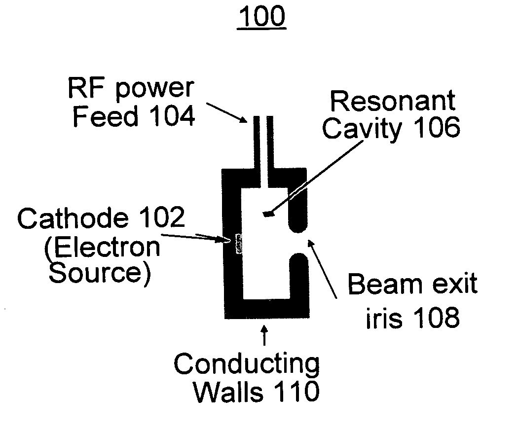
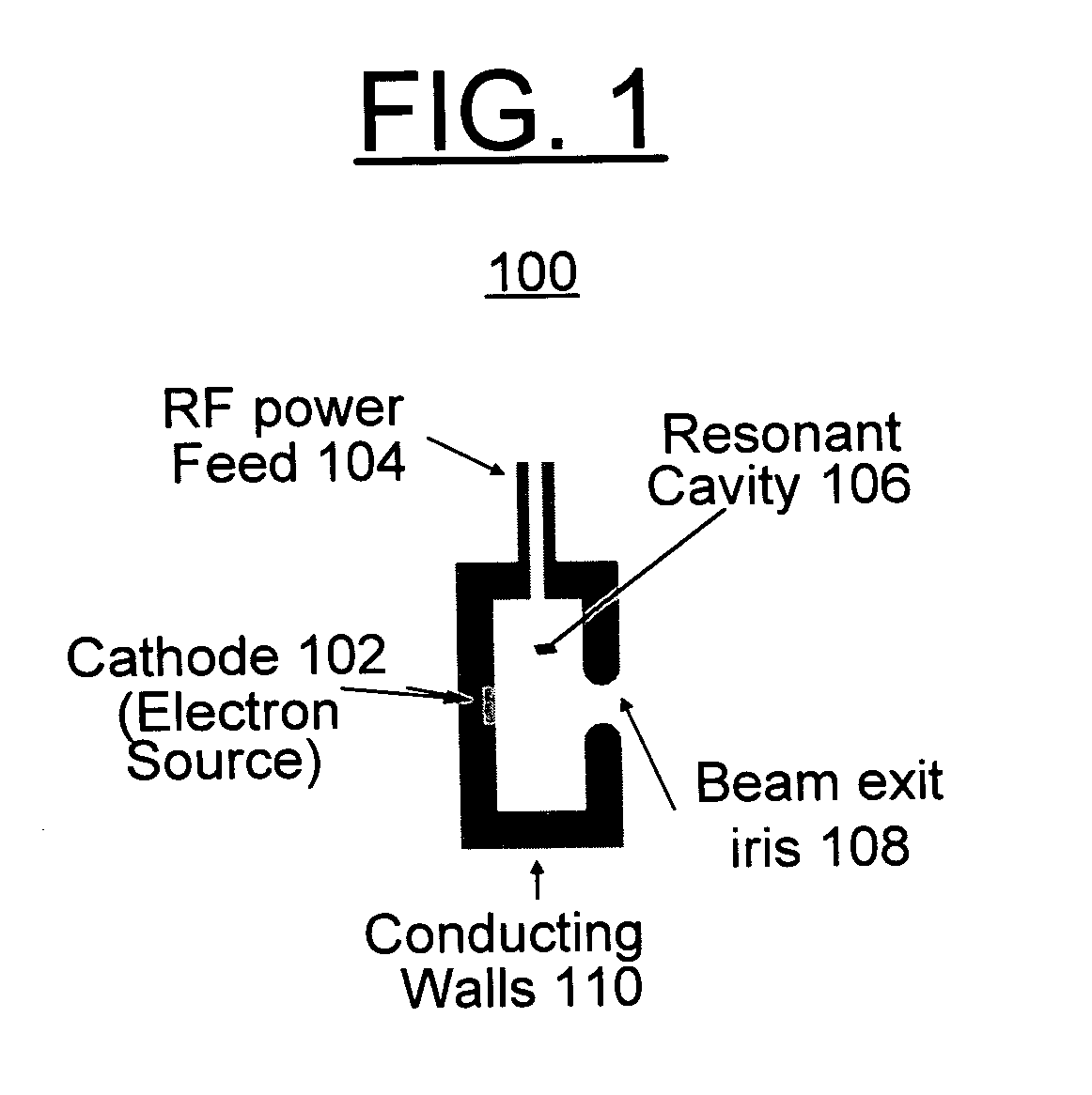
[0034] In accordance with features of the invention, beam processing methods including e-beam welding and e-beam evaporation for thin film deposition are implemented using a novel high power, long focus electron source. The electron source includes a radio frequency (RF) electron gun with a field-emitter cathode providing a focused electron beam and implements a general method for altering the emission time of a field-emitter cathode with respect to the RF period in the gun. This approach combines the advantages of the thermionic-cathode RF electron gun (beam produced every RF period, no laser needed) with those of a photoinjector (gated emission at the most desirable time, high brightness, superconducting RF-compatible). The resulting high power, long focus electron source enables broad applicability across a number of fields.

[0035] In accordance with features of the novel high power, long focus electron source, a planar focusing cathode, also referred to as a standoff cathode, pr...


PUM


Abstract

Beam processing methods including e-beam welding and e-beam evaporation for thin film deposition are implemented with a novel high power, long focus electron source. The high power, long focus electron source generates an e-beam. The e-beam is transported through a series of steering magnets to steer the beam. At least one refocusing magnet is provided to refocus the e-beam. A final steering magnet bends the e-beam to focus on a target, such as a weld joint or a deposition target.

Description

[0001] This application claims the benefit of U.S. Provisional Application No. 60 / 611,629, filed on Sep. 21, 2004.CONTRACTUAL ORIGIN OF THE INVENTION [0002] The United States Government has rights in this invention pursuant to Contract No. W-31-109-ENG-38 between the United States Government and Argonne National Laboratory.FIELD OF THE INVENTION [0003] The present invention relates to novel applications of the invention disclosed in U.S. Ser. No. 10 / 887,142 filed Jul. 8, 2004 (ANL-IN-04-039), entitled FIELD EMISSION CATHODE GATING FOR RF ELECTRON GUNS AND PLANAR FOCUSING CATHODES which embodied a method for implementing a unique electron gun, thus allowing high quality electron beams with high repetition rates to be produced. More particularly, the present invention relates to beam processing methods, including e-beam welding and e-beam evaporation for thin film deposition implemented with a high power, long focus electron source. DESCRIPTION OF THE RELATED ART [0004] Currently, ele...

Claims


Application Information

Patent Timeline
Patent Type & Authority Applications(United States)
IPC IPC(8): H01J23/08
CPCH01J3/021H01J37/065H01J37/073H01J2237/3132H01J2201/317H01J2237/303H01J2237/3104H01J37/305
Inventor LEWELLEN, JOHN W.NOONAN, JOHN
Owner UCHICAGO ARGONNE LLC
Why Eureka
Try Eureka