Low arc AC contactor

a contactor and low-arc technology, applied in the direction of emergency protective arrangement details, emergency protective arrangement for limiting excess voltage/current, electrical equipment, etc., can solve the problems of high power consumption, shortening the life of the contactor, and burning out the contactor, etc., to achieve compact size, low power consumption, and high safety factor

Inactive Publication Date: 2006-03-23
FAT KWONG TSE
View PDF3 Cites 37 Cited by
  • Summary
  • Abstract
  • Description
  • Claims
  • Application Information

AI Technical Summary

Benefits of technology

[0025] 1. The multifunctional low arc contactor of the present invention is able to lay previously current in a capacitor in store for generating a pulse current by electronic circuit, so that when the pulse current passes through the coil of the contactor a strong pulse magnetic field is induced and by means of which its mechanical contacts are engaged together. At the same time, such a engaging condition is kept by using the mechanical self-locking method (see FIG. 1, 10A) or polarized magnetic field self-locking method. When the contacts need to be disengaged, the self-locking is released in the same manner as the above, i.e., by means of current stored in the capacitor. Therefore the contactor has low power consumption, compact size, and high in safe factor. Since the pulse current is applied to the coils, th

Problems solved by technology

According to the requirements of the on-off procedure of the load circuit, as the mechanical contacts need to be in an engaging condition for a long time, the power for generating magnetic field must be continuously supplied to the coil for that period to retain the magnetic field, thus resulting in a higher consumption of power and bulky coil.
However, as the load current is high or a short circuit occurs, a powerful arc will be generated so that the contacts are burn out or the life span thereof is shorten.
Therefore, conventional contactor is generally equipped with metal or ceramic components as a heat sink an

Method used


Image

  • Low arc AC contactor
  • Low arc AC contactor
  • Low arc AC contactor

Examples


Embodiment Construction

[0038] An embodiment of a multifunctional low arc AC contactor of the present invention is illustrated in FIGS. 1-7.

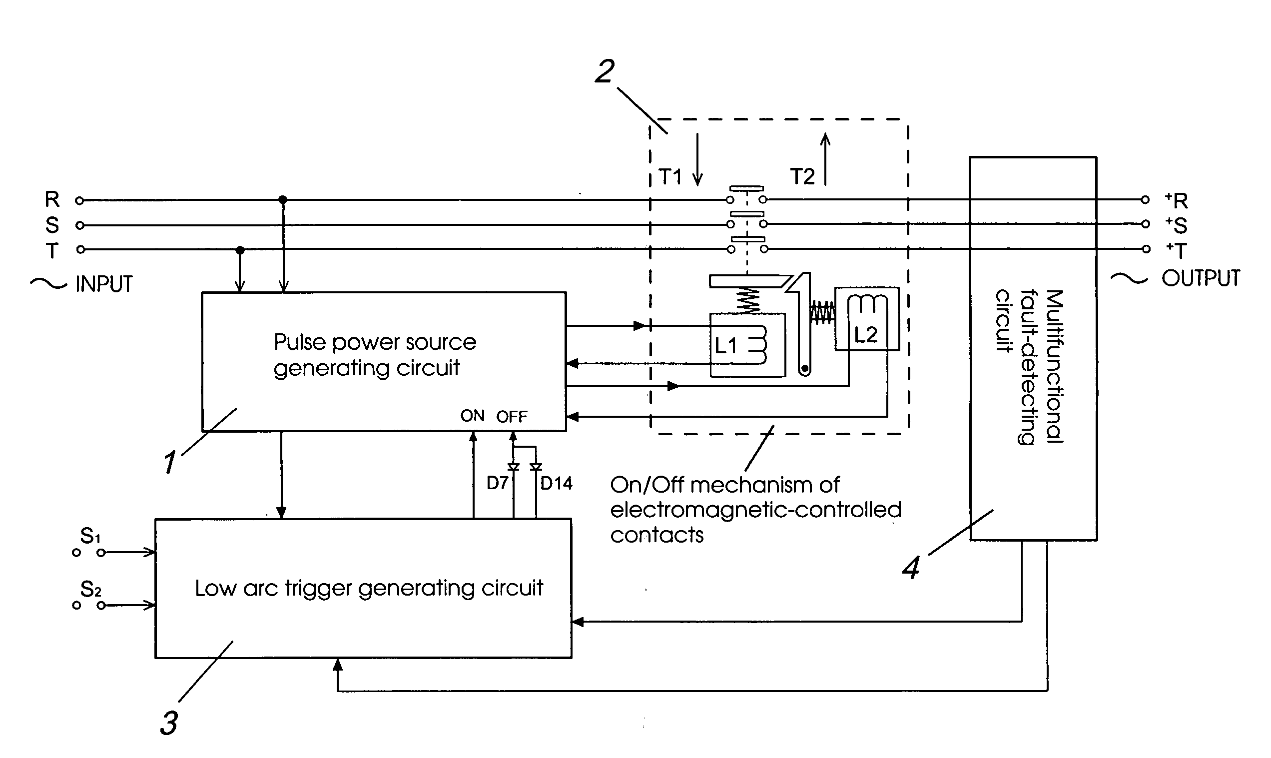
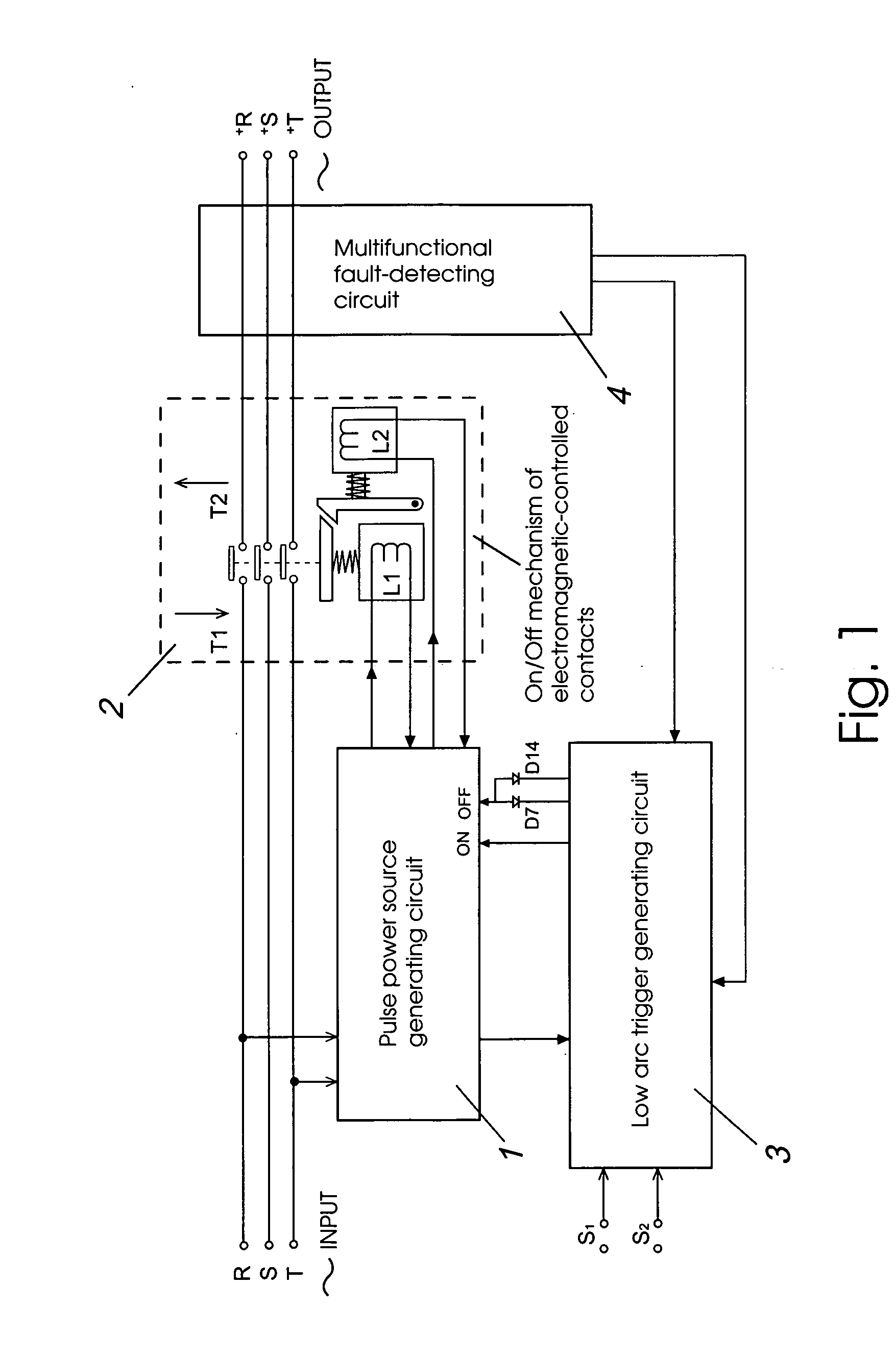
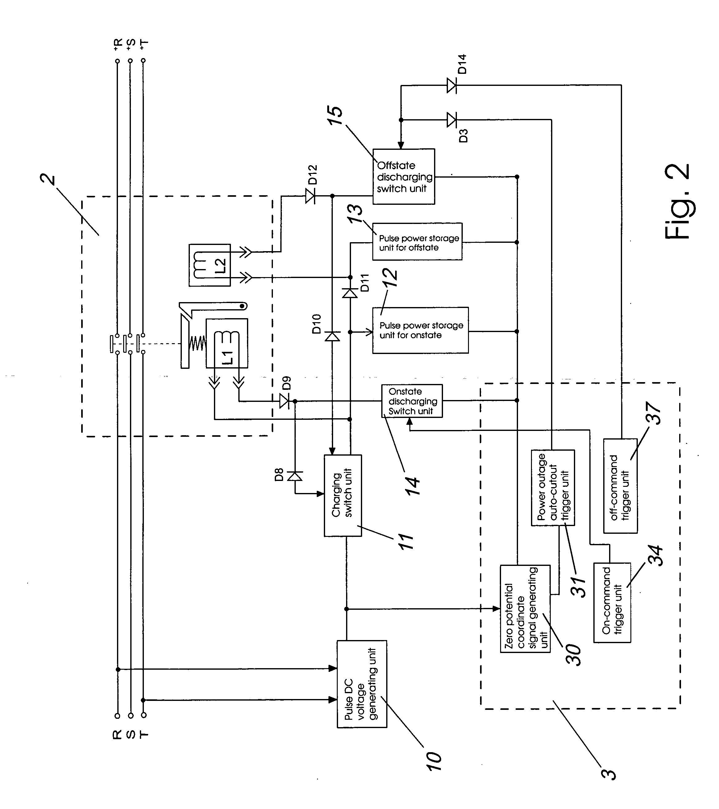
[0039] Referring now to FIG. 1, FIG. 2 and FIG. 3, the low arc AC contactor of the present invention includes a mechanism 2 for engaging / disengaging electromagnetic-controlled contacts, wherein the contacts are connected to AC power supply and the load; a pulse power source generating circuit 1, which is two-way electrically connected with coil L1 and a coil L2 in the on / off mechanism 2 of the electromagnetic-controlled contacts; as well as low arc trigger generating circuit 3, by which a pulse DC signal from the pulse power source generating circuit 1 is received the lowest potential of the AC voltage is detected, and an on-command low arc triggering signal is transmitted to the pulse power source generating circuit 1 in order to generate strong current to induce strong pulse magnetic field in coil L1, thus engaging the contacts, and an off-command low arc triggering...


PUM


Abstract

A low arc AC contactor comprises an on/off mechanism electromagnetic-controlled contact, a pulse power source generating circuit, a low arc trigger generating circuit, and a multifunctional fault-detecting circuit. The contactor converts an instantaneous strong current into strong pulse magnetic field energy to actuate contacts of mechanical portion of the contactor, so that the power source load is on or off. Each of the actuating process will be controlled by the electric circuit to perform at the lowest potential of AC voltage for reducing arc's destructive power. Moreover, the contactor uses photoelectric coupling circuits, in which it can be controlled by external low voltage signal commands, as well as providing protection from overload, phase loss, short circuit, and leakage current.

Description

BACKGROUND OF THE INVENTION [0001] The present invention relates to an AC (Alternating Current) contactor and, more particularly, to an AC contactor in which, during the lowest potential of an AC source, its mechanical contacts are operated upon a large magnetic force converted from an instantaneous strong current in order to control the on or off of AC source load circuit and which may be controlled by external low voltage signal commands, thus providing safety protection from overload, phrase loss, short circuit, leakage current, etc. DESCRIPTION OF RELATED ART [0002] It is well known that commercially available conventional contactors are used for controlling the on or off of the power source load circuit, in which the mechanical contacts are operated upon a magnet field generated by the coil of contactor through that AC or DC flows. According to the requirements of the on-off procedure of the load circuit, as the mechanical contacts need to be in an engaging condition for a long...

Claims


Application Information

Patent Timeline
IPC IPC(8): H02H3/00
CPCH01H9/56H02H3/00H02H1/0015H01H47/226
Inventor CHUN LAM, SHEIR
Owner FAT KWONG TSE
Why Eureka
Try Eureka