Hybrid fastener apparatus and method for fastening

a hybrid fastener and apparatus technology, applied in the direction of fastening means, screws, dowels, etc., can solve the problems of composite structural members delamination, inadequate sealing, inadequate electrical continuity, etc., to reduce the likelihood of delamination, improve the electrical continuity of structural members, and reduce the effect of galvanic corrosion

Inactive Publication Date: 2006-03-23
THE BOEING CO
View PDF98 Cites 52 Cited by
  • Summary
  • Abstract
  • Description
  • Claims
  • Application Information

AI Technical Summary

Benefits of technology

[0008] The present invention provides fasteners and methods for fastening non-metallic and metallic structural members. The fasteners can be formed at least partially of composite materials, e.g., as a hybrid fastener formed partially of a composite material and partially of a metallic material. The fasteners can be compatible with the materials of the structural members to be fastened, such as where one or more of the structural members is formed of a composite material. Thus, the composite material of the fastener can reduce the galvanic corrosion that might otherwise result if a co

Problems solved by technology

Therefore, the fasteners often have physical characteristics that are dissimilar to or incompatible with the composite materials of the structural members being fastened.
In some cases, the use of dissimilar materials can result in delamination of the composite structural members caused by the fastener under installation and operational loads, inadequate sealing surrounding the fastener and therefore leakage of fluids through the joined components, inadequate electrical continuity between the composite components and arcing across the gaps surrounding the fasteners, galvanic corrosion between the fasteners and components at the composite joint, increased weight of the joined components, and/or nonuniform coefficients of thermal expansion between the fastener material and the surrounding composite material.
However, the dissimilarity of the metallic fastener m

Method used


Image

  • Hybrid fastener apparatus and method for fastening
  • Hybrid fastener apparatus and method for fastening
  • Hybrid fastener apparatus and method for fastening

Examples


Embodiment Construction

[0024] The present invention now will be described more fully hereinafter with reference to the accompanying drawings, in which some, but not all embodiments of the invention are shown. Indeed, this invention may be embodied in many different forms and should not be construed as limited to the embodiments set forth herein; rather, these embodiments are provided so that this disclosure will satisfy applicable legal requirements. Like numbers refer to like elements throughout.

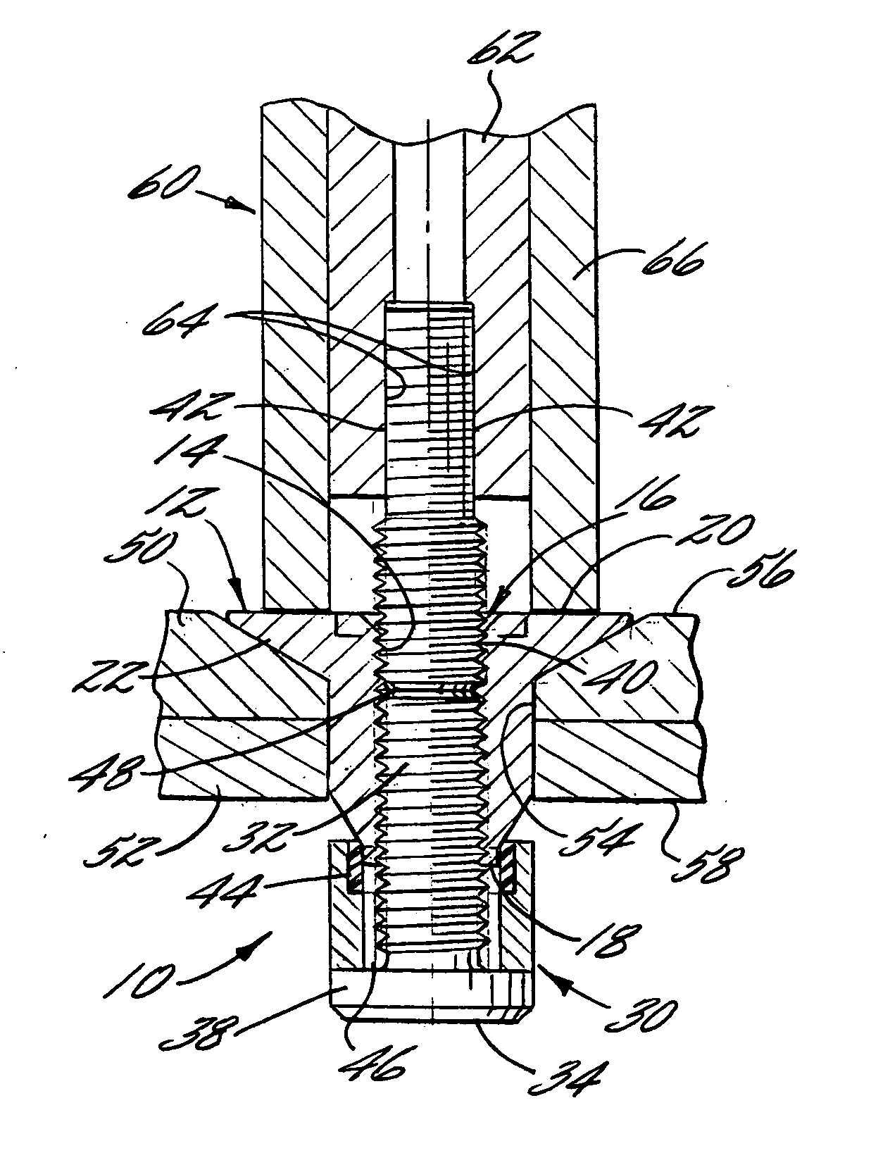
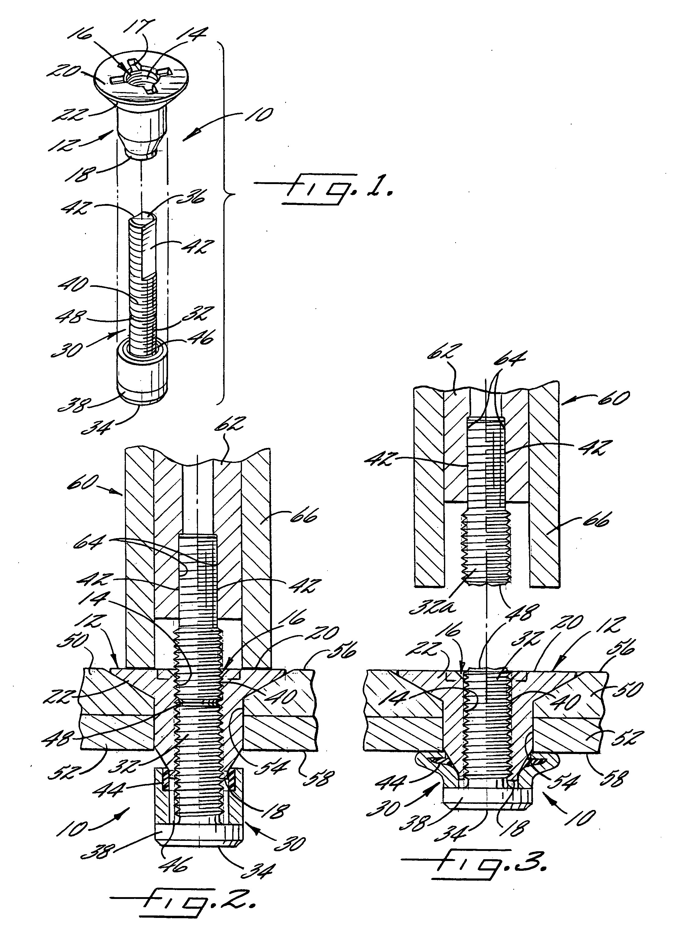
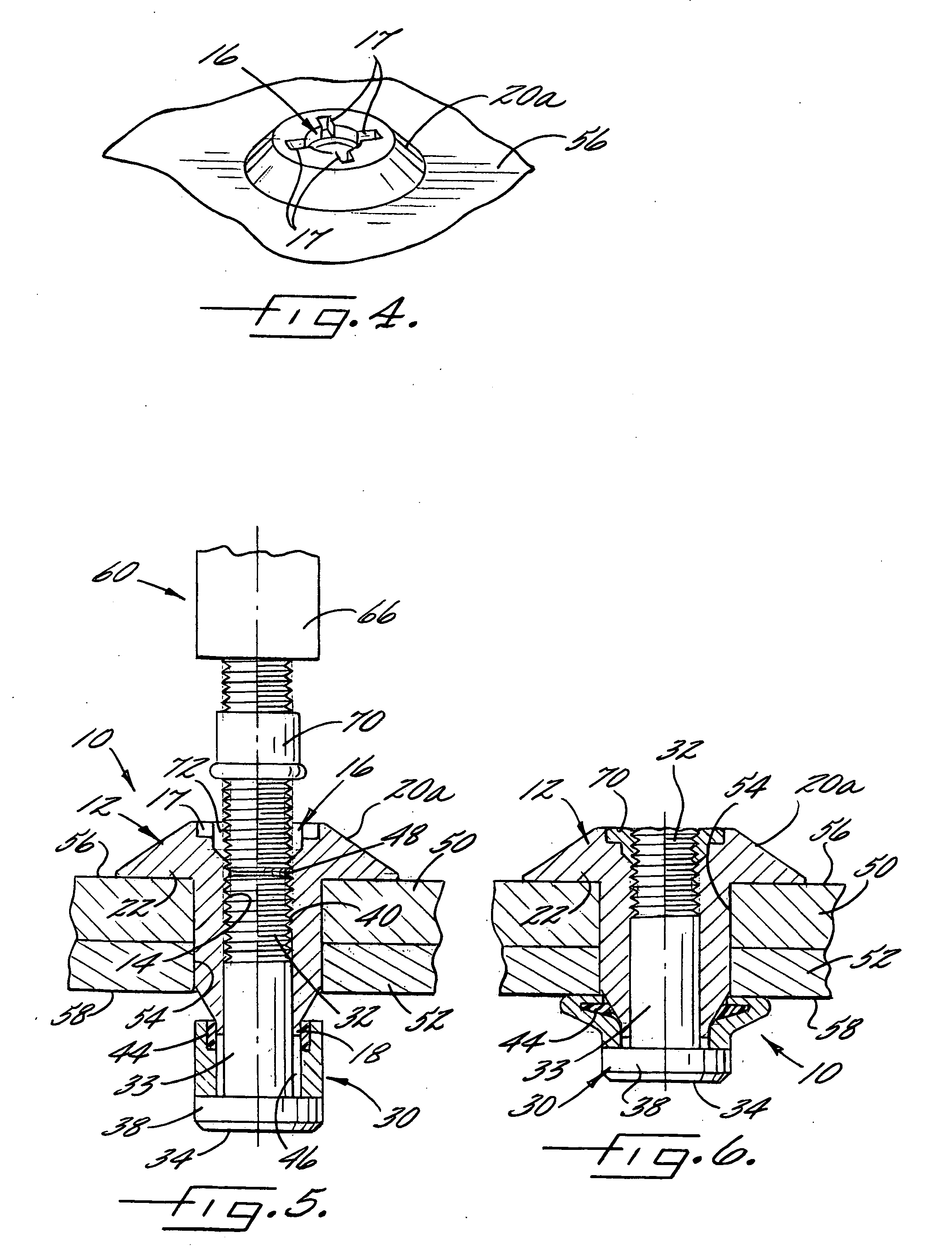
[0025] Referring now to the drawings, and in particular to FIG. 1, there is illustrated a composite-metallic hybrid fastener 10, which can be used for fastening structural members. In particular, as shown in FIGS. 2 and 3, the fastener 10 can be installed in an aperture 54 that extends between first and second sides 56, 58 of the structural members 50, 52 to thereby fasten the structural members 50, 52. The fastener 10 is compatible with various types of structural members. For example, the fastener 10 can be us...


PUM


Abstract

A fastener and method for fastening structural members wherein the fastener comprises a metallic stem defining a shank extending between first and second ends, the stem defining a deformable first head at the first end of the shank, and a resin-fiber composite sleeve defining the second end of the shank. The sleeve defines an aperture longitudinally extending through the sleeve, and a portion of the sleeve has a cross-sectional dimension greater than a cross-sectional dimension of the aperture through the structural members. Tensile strength of the composite sleeve is increased by incorporation of a support washer into the composite sleeve and/or by substantially orienting the fibers of the resin-fiber sleeve composite in the longitudinal direction of the sleeve.

Description

BACKGROUND OF THE INVENTION [0001] 1) Field of the Invention [0002] The present invention relates to composite fasteners for fastening structural members, i.e., fasteners formed at least partially of a composite material, such as hybrid fasteners formed of a combination of composite and metallic materials, and / or blind composite fasteners. [0003] 2) Description of Related Art [0004] High-strength composite materials are increasingly being used in the manufacture of various types of structural members due to improved physical properties and economic availability of the materials. Along with this increased use, the composite materials are more commonly being used in conjunction with metallic components in situations that require structural integrity and fatigue resistance. For example, structural members for aerospace applications that are formed of high-strength composites such as carbon / epoxy, polyaramid / epoxy, or glass / epoxy composites are mechanically fastened using high-strength ...

Claims


Application Information

Patent Timeline
IPC IPC(8): F16B13/04
CPCF16B19/08F16B33/006F16B19/1063
Inventor KEENER, STEVEN G.
Owner THE BOEING CO
Why Eureka
Try Eureka