

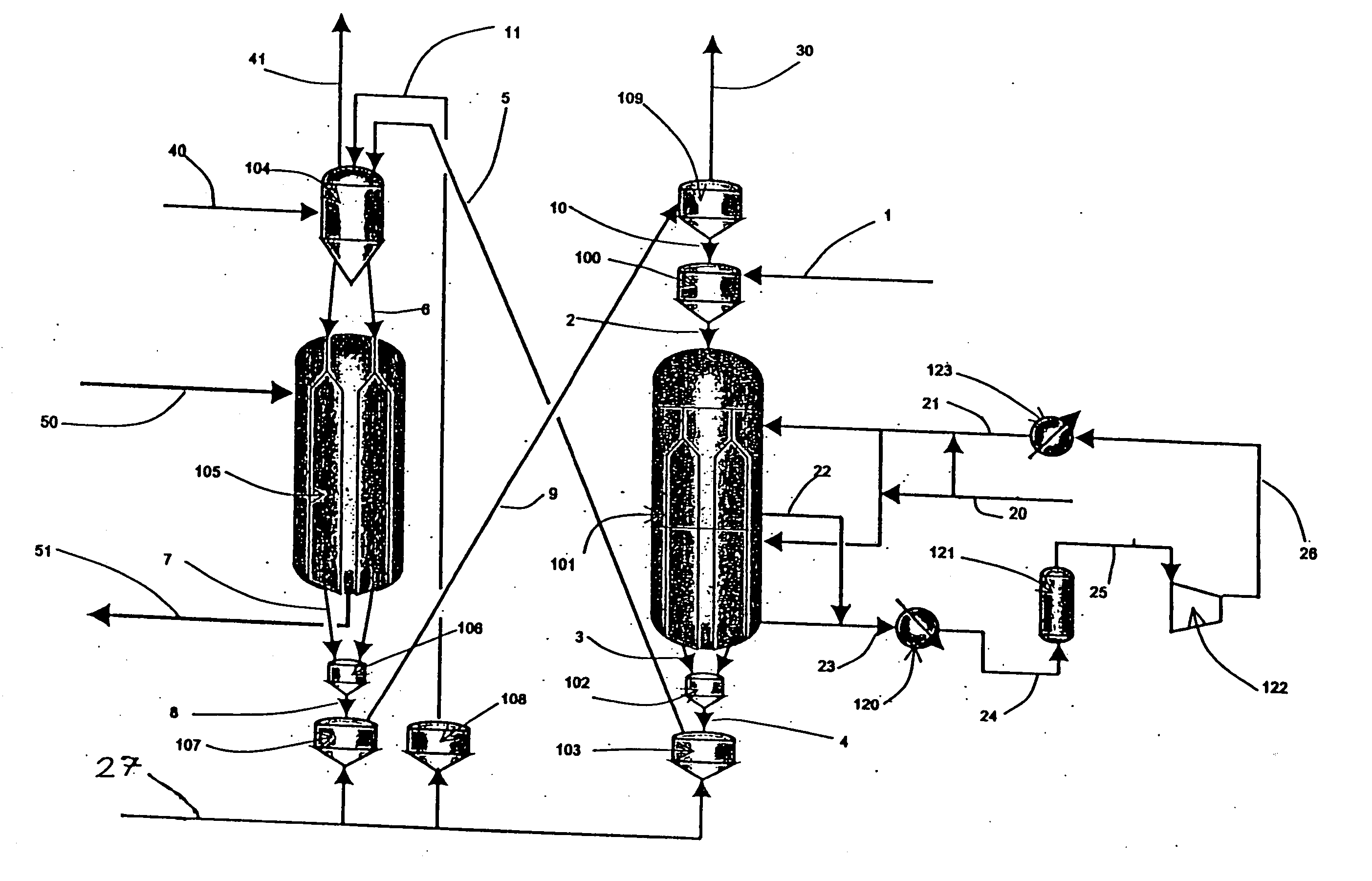
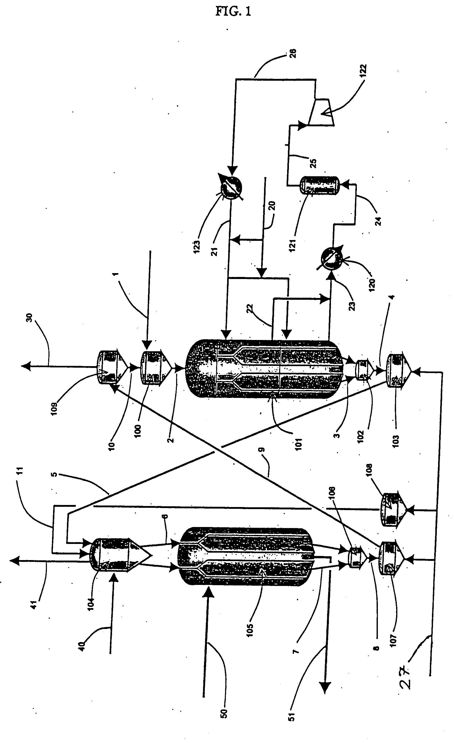
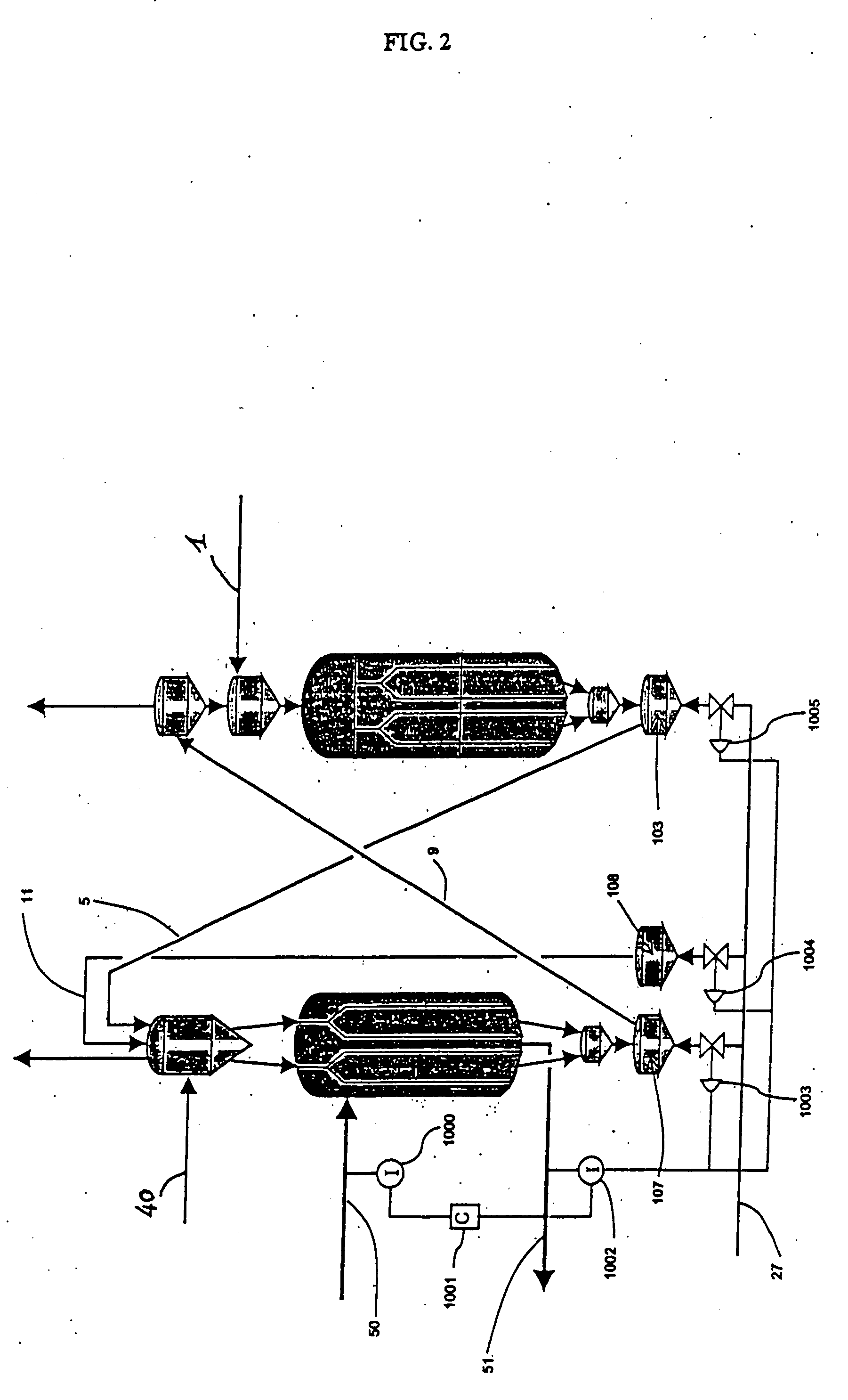
Moving bed process for producing propylene, recycling a fraction of used catalyst
- Summary
- Abstract
- Description
- Claims
- Application Information
AI Technical Summary
Benefits of technology
Problems solved by technology
Method used
Image

Examples
example 1 (
Prior Art)
[0092] In this prior art example, the feed to be treated was constituted by 100% isobutene.
[0093] The feed was injected into a reactor functioning in moving bed mode.
[0094] The catalyst used was a CBV1502 containing 80% MFI type zeolite having a Si / Al ratio of 75. The catalyst was regenerated in a regeneration zone functioning at a temperature of 823 K and at a pressure of 0.10 MPa.
[0095] The cycle time for the catalyst was 48 hours. The reaction was carried out at a temperature of 853 K and at a total pressure of 0.12 MPa. The liquid space velocity was 4.5 h−1.
[0096] The compositions obtained at the outlet from the reactors are shown in Table 1.
TABLE 1Composition at outlet from moving bed with no catalyst recycle.CompoundComposition (wt %)Methane1.92Ethylene15.30Ethane1.00Propylene24.95Propane5.22Isobutane4.02Isobutene5.211-butene2.60Butane2.50Trans-2-butene3.19Cis-2-butene2.403-methyl-1-butene0.14Isopentane0.691-pentene0.232-methyl-1-butene0.71Pentane0.24Trans-2-pe...
example 2 (
in Accordance with the Invention)
[0098] In this example, the feed to be treated and the catalyst were the same as those used in Example 1 (prior art). 49% by weight of the flow of used catalyst was directly recycled to the head of the moving bed reactor mixed with a complementary 51% of regenerated catalyst. The catalyst was regenerated under the same conditions as those in Example 1 (prior art).
[0099] The compositions obtained at the outlet from the reactors are shown in Table 2.
TABLE 2Composition at outlet from moving bed with used catalyst recycle.CompoundComposition (wt %)Methane0.73Ethylene9.61Ethane0.36Propylene28.97Propane2.08Isobutane2.15Isobutene12.981-butene6.38Butane1.80Trans-2-butene7.90Cis-2-butene5.993-methyl-1-butene0.29Isopentane0.341-pentene0.482-methyl-1-butene1.44Pentane0.16Trans-2-pentene1.19Cis-2-pentene0.672-methyl-2-butene2.59Trans-1,3-pentadiene0.06Cis-1,3-pentadiene0.06Cyclopentene0.22Cyclopentane0.40Others (C6+)13.16Total100
[0100] The performance of the ...
example 3 (
Prior Art)
[0102] In this prior art example, the feed to be treated was constituted by 100% isobutene.
[0103] The feed was injected into a reactor functioning in moving bed mode.
[0104] The catalyst used was a CBV28014 containing 30% of MFI type zeolite having a Si / Al ratio of 140. The catalyst was regenerated at a temperature of 823 K and at a pressure of 0.10 MPa.
[0105] The cycle time for the catalyst was 48 hours. The reaction was carried out at a temperature of 783 K and at a total pressure of 0.12 MPa. The liquid space velocity was 1.7 h−1.
[0106] The compositions obtained at the outlet from the reactors are shown in Table 3.
TABLE 3Composition at outlet from moving bed with no catalyst recycle.CompoundComposition (wt %)Methane0.10Ethylene3.63Ethane0.08Propylene23.61Propane1.46Isobutane2.19Isobutene14.081-butene6.71Butane1.51Trans-2-butene9.97Cis-2-butene7.303-methyl-1-butene0.47Isopentane0.671-pentene0.702-methyl-1-butene2.72Pentane0.29Trans-2-pentene2.06Cis-2-pentene1.102-me...
PUM
 Abstract
Description
Claims
Application Information