

Wiring board and wiring board manufacturing method
- Summary
- Abstract
- Description
- Claims
- Application Information
AI Technical Summary
Benefits of technology
Problems solved by technology
Method used
Image

Examples
embodiment
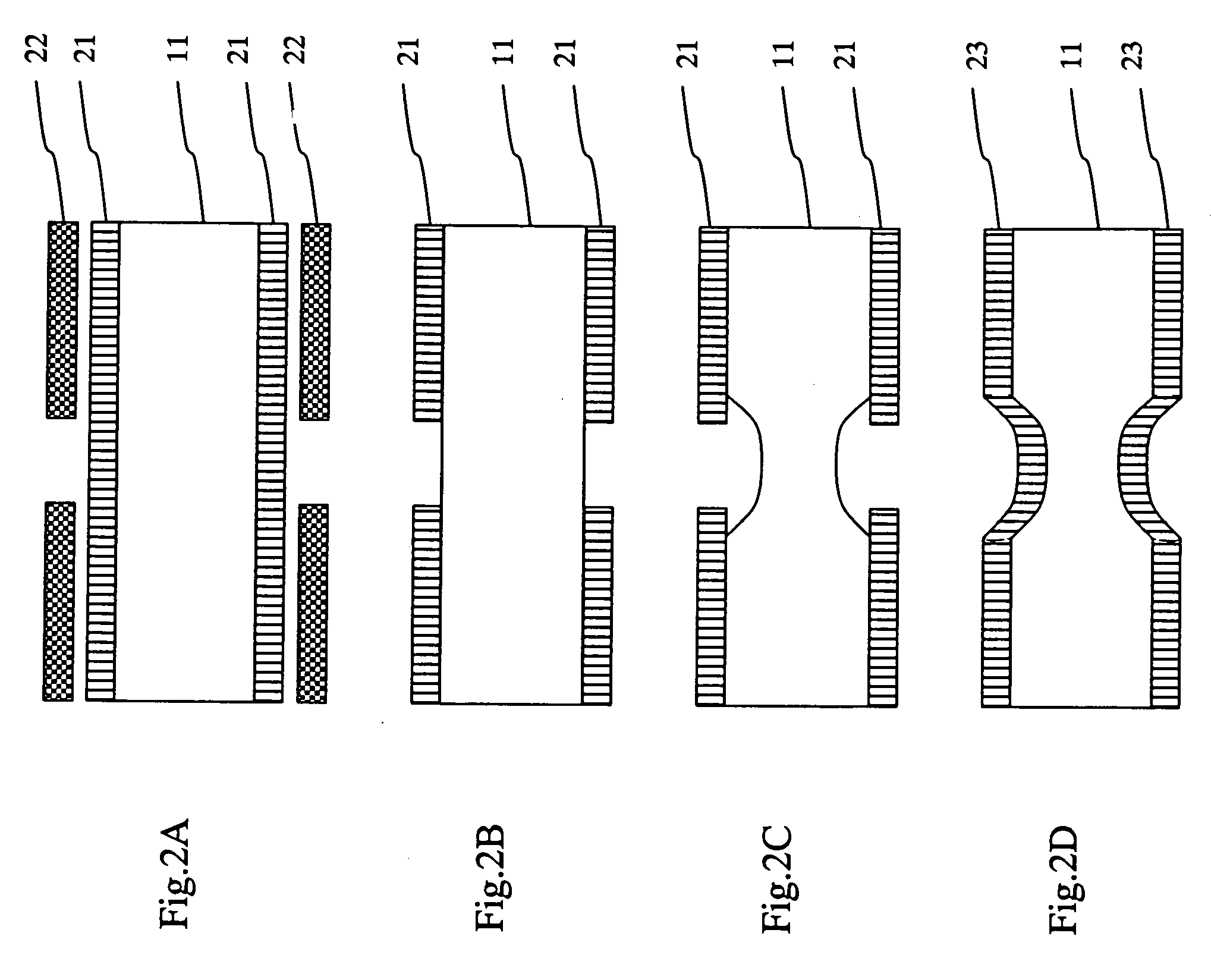
[0048] Next, an embodiment of the method for manufacturing a wiring board, by which through holes are made in the metal plate used for the wiring board as described above, will be described. A manufacturing process includes the first step for performing initial half etching and the second step for performing etching after the first step.
[0049] As the first step, first, a 42-alloy plate of 0.3 mm in thickness as a metal plate was immersed in acetone, thereby being degreased and cleaned, and both surfaces of the immersed degreased cleaned 42-alloy plate were coated with a resist. The both surfaces were spin-coated with a photoresist (OFPR-800, made by Tokyo Ohka Kogyo Co., Ltd.). A pattern for forming the through holes was exposed by a double sided exposure and then was developed by a developing solution (NMD-3, made by Tokyo Ohka Kogyo Co., Ltd.). The developing time was about 60 seconds.
[0050] Next, the 42-alloy plate was subjected to immersion etching by an etching solution of ir...
PUM
 Abstract
Description
Claims
Application Information