Resonator
a resonator and resonator technology, applied in the field of resonators, can solve the problems of large installation space for a resonator, increase the installation space of the resonator, and difficulty in maintaining the desired sound pressure suppression effect for a substantial period of time, and achieve the effect of small installation space, efficient reduction of the sound pressure of the target sound, and large sound pressur
- Summary
- Abstract
- Description
- Claims
- Application Information
AI Technical Summary
Benefits of technology
Problems solved by technology
Method used
Image
Examples
examples
[0075] Measurement tests such as an acoustic excitation test and a numerical value test (transfer-matrix method) executed on the resonator of the embodiment will be described below.
first example
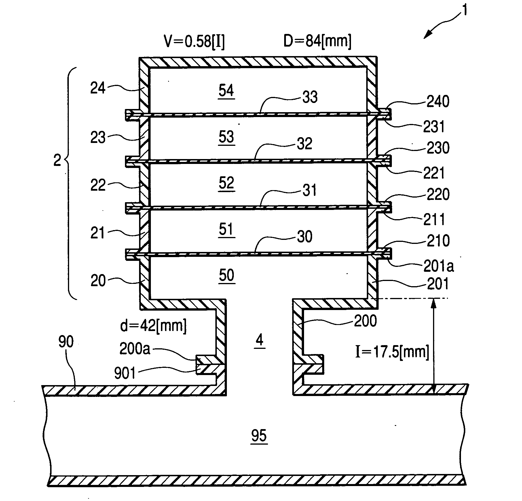
[0076] The acoustic excitation test executed on the resonator 1 shown in FIG. 7 will be described.
[0077] [Test sample]
[0078] The specifications of the resonator 1 shown in FIG. 7 will be described. The volume V of the cavity chamber is 0.58 l (liters). The inner diameter D of the cavity chamber is 84 mm. The axial length l of the communication pipe 4 is 17.5 mm. The inner diameter d of the communication pipe 4 is 42 mm. The spring constant k of the diaphragms 30 through 33 is 34.7 N / m. The density p of the diaphragms 30 through 33 is 8.70×10² kg / M3. The thickness t of the diaphragms 30 through 33 is 0.5 mm. The resonator 1 having such specifications is called Example 1.
[0079] [Test Method]
[0080] Next, the acoustic excitation test will be described. The acoustic excitation test uses a straight tubular pipe having an entire length of 0.6 m whose ends are open, a loudspeaker, and a microphone. To the side wall at the middle section of the straight tubular pipe branches the resonator ...
example 2
[0086] Calculation result of the transfer-matrix method executed on the test samples shown below will be described.
[0087] [Test Sample]
[0088] Specifications of test samples will be described. FIG. 9 is a schematic view of the test sample in Example 2-1. FIG. 10 is a schematic view of the test sample in Example 2-2. FIG. 11 is a schematic view of the test sample in Comparison Example 2-1. FIG. 12 is a schematic view of the test sample in Comparison Example 2-2. In these drawings, sections corresponding to FIG. 7 are given same signs.
[0089] Example 2-1 shown in FIG. 9 arranges diaphragms 30a through 30i in Comparison Example 2-1 shown in FIG. 11 (side branch resonator). A branch pipe 2 shows a shape of a cylinder with a bottom. The spring constant k of the diaphragms 30a through 30i is 139 N / m. The density p of the diaphragms 30a through 30i is 8.70×10² kg / M3. The thickness t of the diaphragms 30a through 30i is 0.5 mm. The inner diameter d′ of the branch pipe 2 in Example 2-1 (FIG....
PUM
 Abstract
Description
Claims
Application Information
 - R&D
- Intellectual Property
- Life Sciences
- Materials
- Tech Scout
- Unparalleled Data Quality
- Higher Quality Content
- 60% Fewer Hallucinations
Browse by: Latest US Patents, China's latest patents, Technical Efficacy Thesaurus, Application Domain, Technology Topic, Popular Technical Reports.
© 2025 PatSnap. All rights reserved.Legal|Privacy policy|Modern Slavery Act Transparency Statement|Sitemap|About US| Contact US: help@patsnap.com


