Duplexer
a dual-port, filter technology, applied in the direction of electrical equipment, multiple-port networks, electric/electrostrictive/magnetostrictive devices, etc., can solve the problems of reducing the filter characteristics of the desired filter, affecting the transmission and receiving signals, and reducing the filter characteristics of conventional techniques
- Summary
- Abstract
- Description
- Claims
- Application Information
AI Technical Summary
Benefits of technology
Problems solved by technology
Method used
Image
Examples
first embodiment
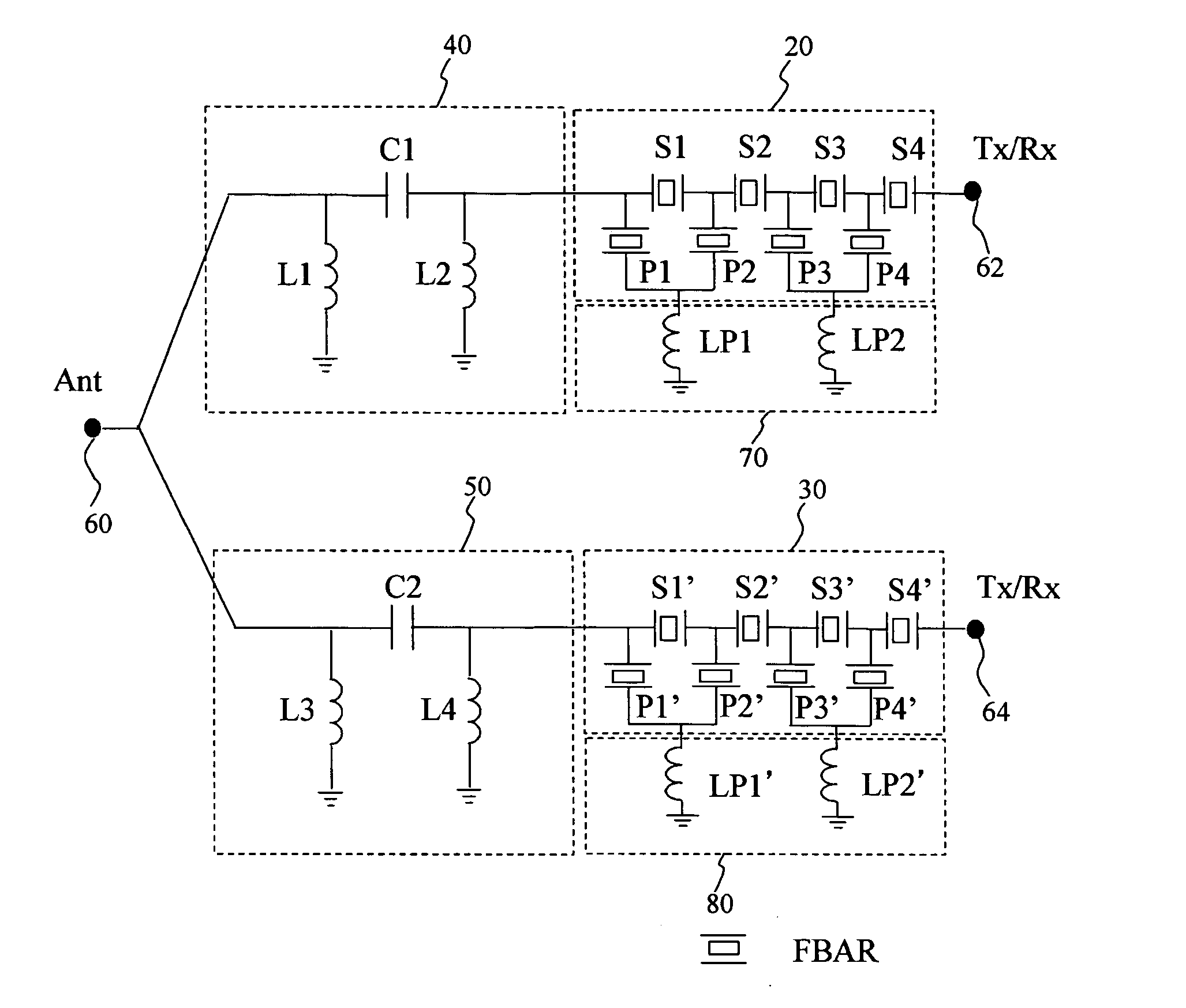
[0053]FIG. 6 shows the fundamental structure of a duplexer according to an embodiment of the present invention. The duplexer has a first FBAR filter 20, a second FBAR filter 30, a first integrated-passive device (hereinafter simply referred to as IPD) 40, and a second IPD.50. These structural elements are sealed within a package 10. An antennal terminal 60 and transmit / receive terminals (Tx / Rx) 62 and 64 are attached to the package 10. In a case where the first FBAR filter 20 and the second FBAR filter 30 are a transmit filter and a receive filter, respectively, the terminals 62 and 64 are a transmit terminal and a receive terminal, respectively. The first IPD 40 is provided between the antenna terminal 60 and the first FBAR filter 20. Similarly, the second IPD 50 is provided between the antenna terminal 60 and the second FBAR filter 30. As will be described in detail later, the package 10 has electrically conductive patterns, which realize an inductance between the first FBAR filte...
second embodiment
[0077] The first and second IPDs 40 and 50 for the phase shifters will be further considered. The phase shifters are required to have matching performance and low insertion loss.
[0078] First, the matching performance is considered. In order to realize good matching performance, it is preferable to use lumped-parameter type elements composed of three structural elements as shown in FIGS. 22A through 22D. FIG. 22A shows a n-type L-C-L circuit in which a capacitor C01 is connected in series between the input and output terminals, and inductors L01 and L02 are connected in parallel therebetween. FIG. 22B shows a T-type C-L-C circuit in which the capacitors C01 and C02 are connected in series between the input and output terminals, and the inductor L01 is connected in parallel therebetween. FIG. 22C shows a T-type L-C-L circuit in which the inductors L01 and L02 are connected in series between the input and output terminals and the capacitor C01 is connected in parallel therebetween. FI...
third embodiment
[0101]FIG. 33 is a circuit diagram of a duplexer according to a third embodiment of the present invention. This duplexer is equipped with the phase shifters each composed of two elements shown in FIG. 25A. In addition to the structure of the duplexer according to the second embodiment, the present invention includes capacitors C1 and C2, which are respectively provided in the first and second IPDs 40 and 50 (phase matching circuits) and are connected between the antenna terminal 60 and the first and second filters 20 and 30. The other structures and connections are the same as those of the second embodiment. The duplexer shown in FIG. 33 brings about the same advantages as those of the duplexer of the second embodiment.
[0102] The first and second filters 20 and 30 of the duplexers of the second and third embodiments are further described. Although the following description is specifically directed to the first filter 20, it may be applied to the second filter 30. In the second and ...
PUM
 Abstract
Description
Claims
Application Information
 - R&D
- Intellectual Property
- Life Sciences
- Materials
- Tech Scout
- Unparalleled Data Quality
- Higher Quality Content
- 60% Fewer Hallucinations
Browse by: Latest US Patents, China's latest patents, Technical Efficacy Thesaurus, Application Domain, Technology Topic, Popular Technical Reports.
© 2025 PatSnap. All rights reserved.Legal|Privacy policy|Modern Slavery Act Transparency Statement|Sitemap|About US| Contact US: help@patsnap.com


