

Apparatus for estimating direction of arrival of signal
a signal and antenna technology, applied in the direction of instruments, measurement devices, antennas, etc., can solve the problems of increasing circuit complexity, difficult to increase the number of antenna elements without reducing the receiving power, etc., to improve the angular resolution, improve the effect of angular resolution and excellent characteristics
- Summary
- Abstract
- Description
- Claims
- Application Information
AI Technical Summary
Benefits of technology
Problems solved by technology
Method used
Image

Examples
second embodiment
[0032]FIG. 4 shows an array antenna used in a radar apparatus according to the present invention. The base plate forming the antenna surface is divided into an upper bank 30 and a lower bank 32, and the antenna elements arranged on the upper and lower banks 30 and 32 are offset relative to each other in a horizontal direction. With this arrangement, the effective element spacing is reduced to one half, achieving a corresponding increase in the field of view of the radar. In the example shown in FIG. 4, the outermost antenna elements AU0 and AUN−1 on the upper bank are alternately selected for use as the transmitting antenna. The example shown here is an equispaced array, but in the case of a non-equispaced array also, the effective element spacing can be reduced by arranging the antenna elements on one bank so as not to overlap, in position, any of the antenna elements on the other bank when viewed along the horizontal direction. The problem of reduced gain can be solved by arrangin...
third embodiment
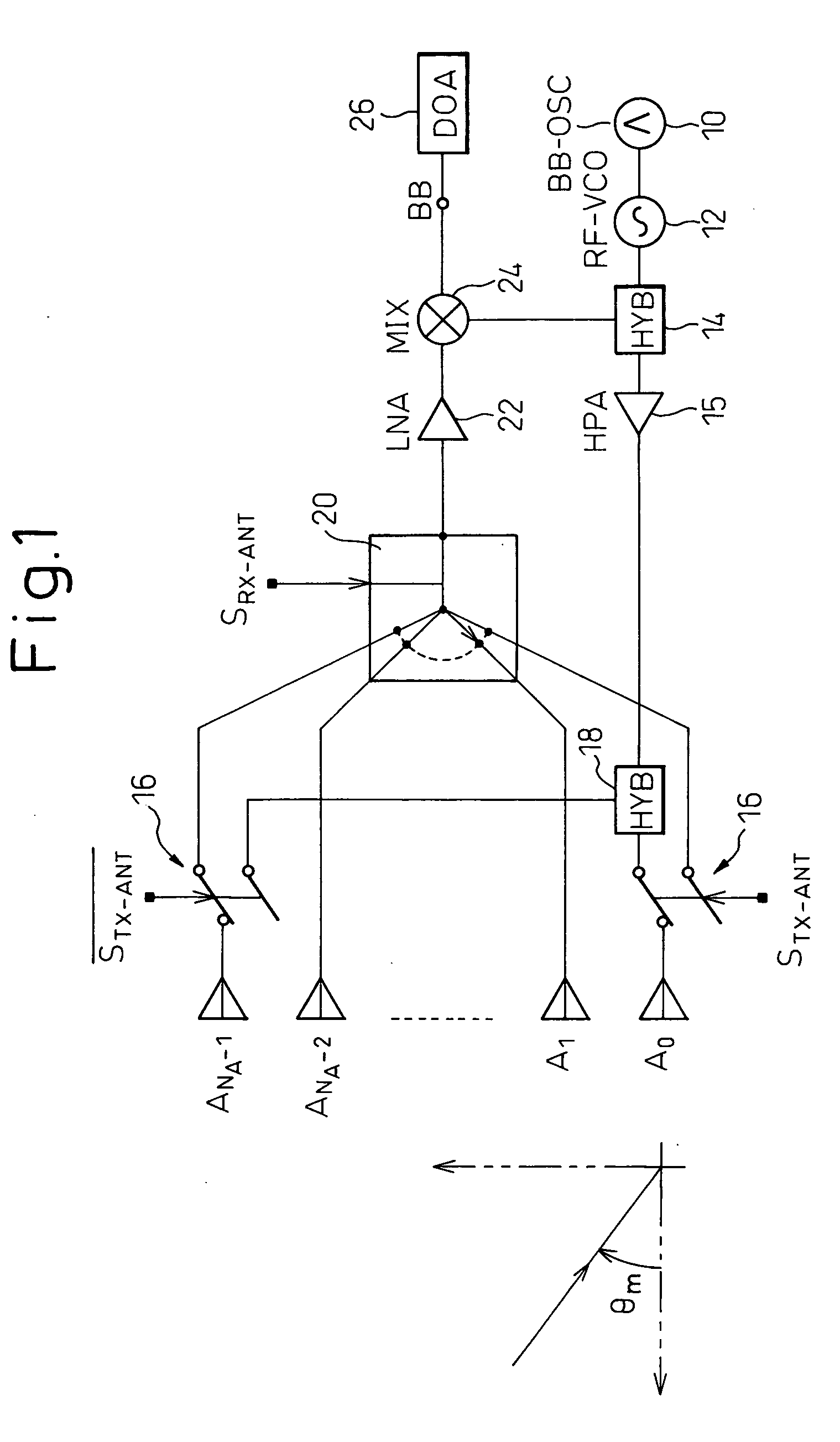
[0033]FIG. 5 shows the configuration of a radar apparatus according to the radar apparatus of FIG. 1; the same component elements as those in FIG. 1 are designated by the same reference numerals, and a description of such elements will not be repeated here.
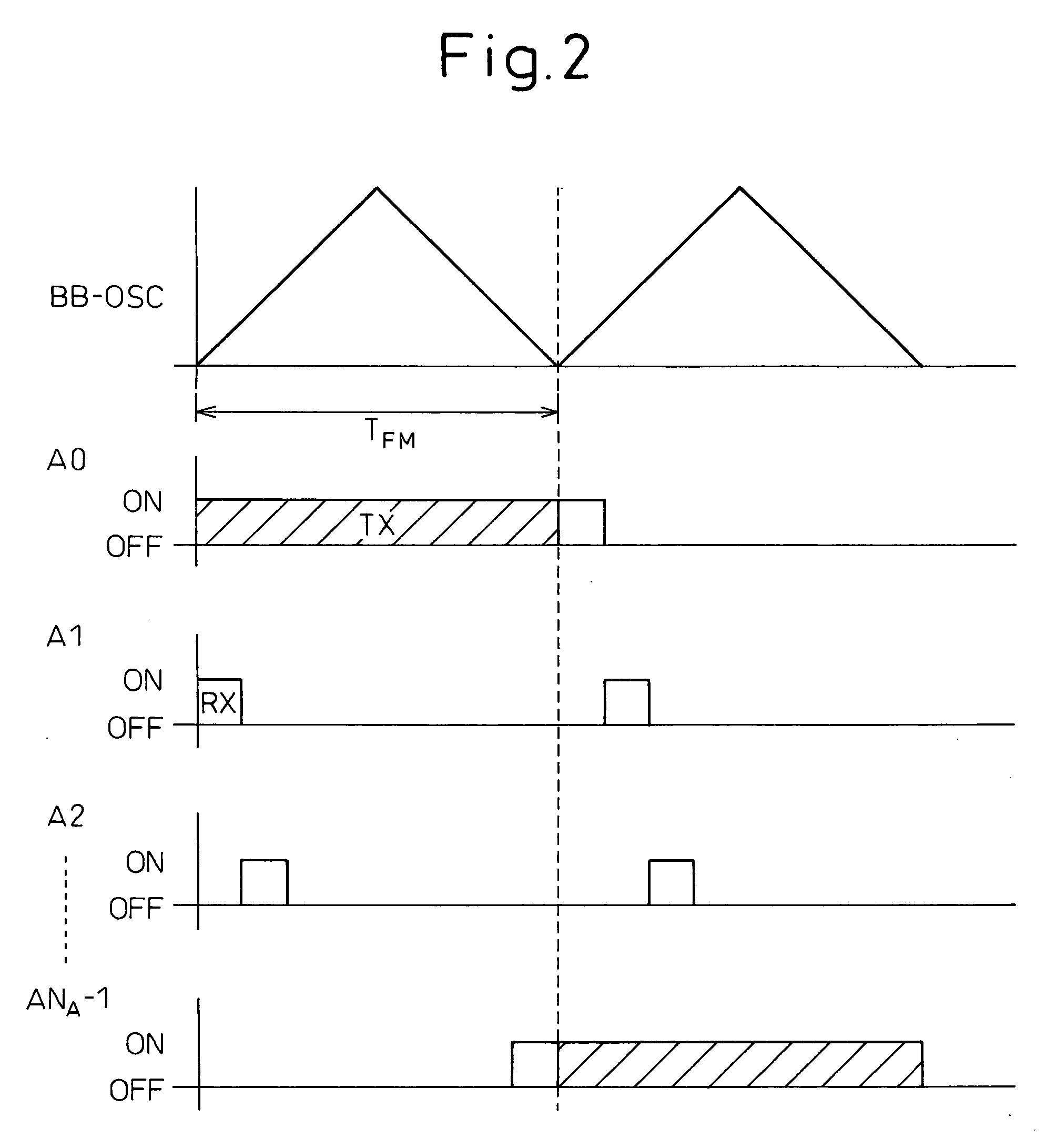
[0034] In a normal mode in which processing is performed to determine the direction of the target by using the method described with reference to FIG. 2, a phase shifter 34 is rendered inoperative with its phase shift amount set to zero, but is made operative in a tracking mode in which target tracking is performed by directing the transmit beam to the target after the direction of the target has been determined in the normal mode. In the tracking mode, the antenna elements A0 and ANA−1 are both connected to the hybrid 18 and thus function as the transmitting antennas. Based on the target's direction θ determined in the normal mode, a direction-of-arrival estimator 26′ determines the phase shift amount φ necessary to direct the tr...
first embodiment
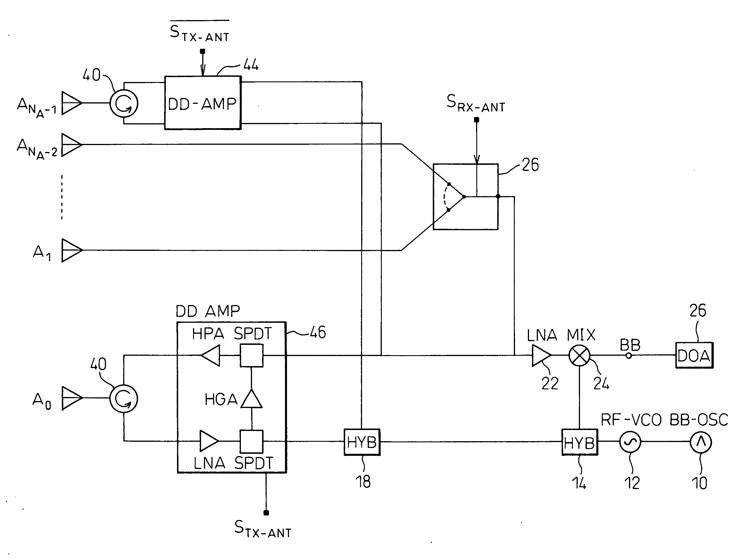
[0037] In the embodiment shown in FIG. 6, the switches 16 used in the first embodiment to switch the outermost antenna elements A0 and ANA−1 between transmit and receive modes are replaced by circulators as duplexers (or unidirectional devices such as hybrids or switches) 40 and 42 and bidirectional amplifier modules (DD-AMP) 44 and 46 which connect the transmitting-side inputs of the respective duplexers 40 and 42 to the transmitter output or connect the receiving-side outputs of the respective duplexers 40 and 42 to the receiver input. When the single-pole double-throw (SPDT) switches in the bidirectional amplifier modules44 and 46 are set as shown in FIG. 7, the receiving-side outputs of the duplexers 40 and 42 are connected via LNA, SPDT, HPA, SPDT, and LNA to the receiver input, that is, the switch 20 in FIG. 6; on the other hand, when they are set as shown in FIG. 8, the transmitter output, that is, the hybrid 18 in FIG. 6, is connected via SPDT, HPA, SPDT, and HPA to the tran...
PUM
 Abstract
Description
Claims
Application Information