Method and system for determining direction of transmission using multi-facet antenna

a multi-facet antenna and antenna technology, applied in direction finders using radio waves, instruments, substation equipment, etc., can solve the problems of difficult to provide, inability to gain access to corporate ethernet networks or internet connections, and difficulty in obtaining communications channels in wireless networks. , to achieve the effect of reducing power consumption, increasing receiver sensitivity to specific units at known locations, and reducing distan

Active Publication Date: 2006-03-30
CHIGUSA TADAAKI
View PDF4 Cites 46 Cited by
  • Summary
  • Abstract
  • Description
  • Claims
  • Application Information

AI Technical Summary

Benefits of technology

[0022] Other aspects of the routing process include registration or detection of transceiver location. Where fixed units are installed in homes, the user can manually describe the location so that, for example, latitude and longitude coordinates could be derived. A built-in GPS receiver could also perform the same task. Another approach is to triangulate transceiver location by using the known or derived locations of other transceivers. Data about various characteristics of units that is useful for routing purposes is maintained in tables (or other forms of storage) in various units, in a central location or both. As units are brought into, taken from, or moved within the network, the routing process (or processes) attempts to maintain desired levels of service.
[0023] One feature of the RF transmitters used in the present invention is the use of antenna arrays for directional transmission. This allows transmitters so-equipped to “steer” a radio beam to specific receivers so that greater distance with less power is achieved. The receiving ability of such antennas is also directional so that receiver sensitivity to specific units at known locations can be increased. Further, this approach reduces the interference from potentially competing signals. This, in turn, increases network efficiency and can, therefore, enhance network density and performance.
[0024] Units can be connected to other wireless or wired networks, such as but not limited to, the Internet, corporate or campus intranets, home networks, etc. Services, such as, streaming of media can be provided within a household or to other designated recipients. Security and access contr

Problems solved by technology

There is no means of gaining access to the corporate Ethernet network or an Internet connection.
Generally, the quality of a communications channel in a wireless network is not guaranteed so that, for example, a software process executing on a device is not guaranteed a specific transfer rate over any given interval of time.
This makes it very difficult to provide, e.g., streaming media such as video and audio.
Other approaches to wireless communications do not provide a comprehensive system design approach.
Bluetooth does include several features for point-to-point communications between devices, but does this based on a master-slave relationship that is difficult to use in a network with changing topology, such as one made up of mobile wireless transceivers.
This clearly limits the operational range of the network.
These shortcomings include, for example, link inefficiency, security problems, roaming issues and network deployment issues.
This leads to a number of problems in the design of the MAC layer.
The MAC layer also does not generally provide any quality of service functions, since it is not required to by the nature of the communication link.
In addition, in some networks, the MAC layer must sense the radio media before transmission, which means that the best link may not be utilized.
In public cellular systems, the keys are usually generated and stored in a central database, which can lead to security problems with respect to access.
However, these techniques require software to run above the radio connection and must also be run by the user prior to any communication between the user and the network.
Howeve

Method used


Image

  • Method and system for determining direction of transmission using multi-facet antenna
  • Method and system for determining direction of transmission using multi-facet antenna
  • Method and system for determining direction of transmission using multi-facet antenna

Examples


Embodiment Construction

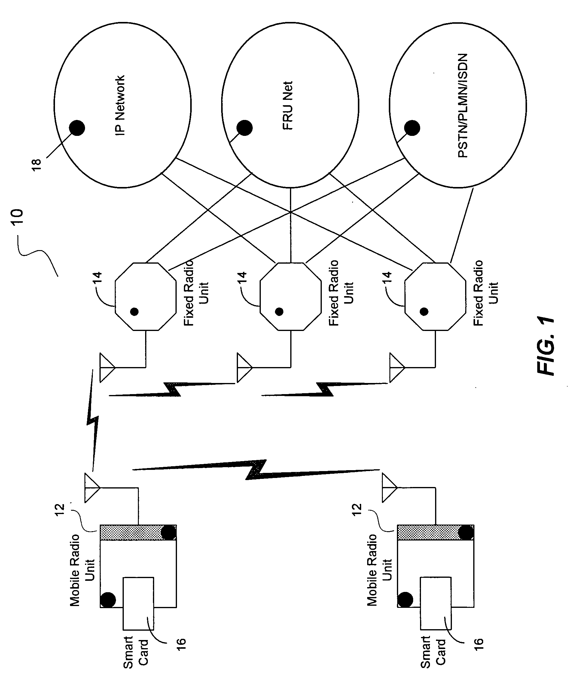
[0040] The present invention in the form of one or more exemplary embodiments will now be described. FIG. 1 is a simplified schematic block diagram illustrating one exemplary embodiment of the present invention. In this exemplary embodiment, the network 10 includes a number of mobile radio units (each an MRU) 12 and a number of semi-fixed or fixed radio units 14 (each an FRU). Based on the disclosure and teachings provided herein, a person of ordinary skill in the art will appreciate that other types of devices that are able to send and receive signals, i.e., transceivers, can be used as MRUs or FRUs in accordance with the present invention.

[0041] In one exemplary embodiment, the MRU 12 is a user portable device that is capable of handling wireless communications. The MRU 12 includes two types of high bandwidth radio, one is used for long range relay communication and the other for shorter range local communication. The MRU 12 is capable of communicating with nearby MRUs and FRUs 1...


PUM


Abstract

A method for determining direction of transmission using an antenna array having a number of panels is disclosed. Each panel is configured to receive signals. According to one aspect of the method, each of the panels is directed to receive signals from a transmitting node. For each panel, a first table having data representing received signal power difference between the panel and a first neighboring panel and a second table having data representing received signal power difference between the panel and a second neighboring panel are built. The panel with the maximum received power is identified. For the identified panel, a first gain table and a second gain table corresponding to its first and second neighboring panels are searched to identify a first transmission angle and a second transmission angle, if any. A transmission angle relative to the transmitting node is determined using the first and second transmission angles.

Description

CROSS-REFERENCES TO RELATED APPLICATION(S) [0001] The present application claims the benefit of priority under 35 U.S.C. § 119 from U.S. Provisional Patent Application Ser. No. 60 / 403,786 entitled “SYSTEM FOR MOBILE BROADBAND NETWORKING USING DYNAMIC QUALITY OF SERVICE PROVISIONING”, filed on Aug. 14, 2002, the disclosure of which is hereby incorporated by reference in its entirety for all purposes.BACKGROUND OF THE INVENTION [0002] The present invention relates in general to network communications and, more specifically, to a method and system for providing an active routing antenna for use in conjunction with fixed and mobile wireless transceivers with dynamic routing based on quality-of-service (QoS) criteria in order to optimize data transfers in a network with dynamically changing topology. [0003] Wireless networks are gaining in popularity. Standards such as IEEE 802.11a, 802.11b, 802.1 μg, Bluetooth, Ultra Wideband (UWB), etc., allow users to connect wirelessly via portions o...

Claims


Application Information

Patent Timeline
IPC IPC(8): G01S5/04
CPCG01S3/18H01Q21/205H04B7/0868H04B7/0686H04B7/0491
Inventor SAYERS, IAN
Owner CHIGUSA TADAAKI
Why Eureka
Try Eureka