
Beam signage and communication system

a communication system and beam technology, applied in the field of beam signage and communication system, can solve the problems of affecting affecting the display, and affecting the display, so as to improve the visibility of the display, facilitate the construction and manipulation, and improve the effect of visibility

Inactive Publication Date: 2006-04-06
STRATH ELGIN
View PDF13 Cites 6 Cited by
  • Summary
  • Abstract
  • Description
  • Claims
  • Application Information

AI Technical Summary

Benefits of technology

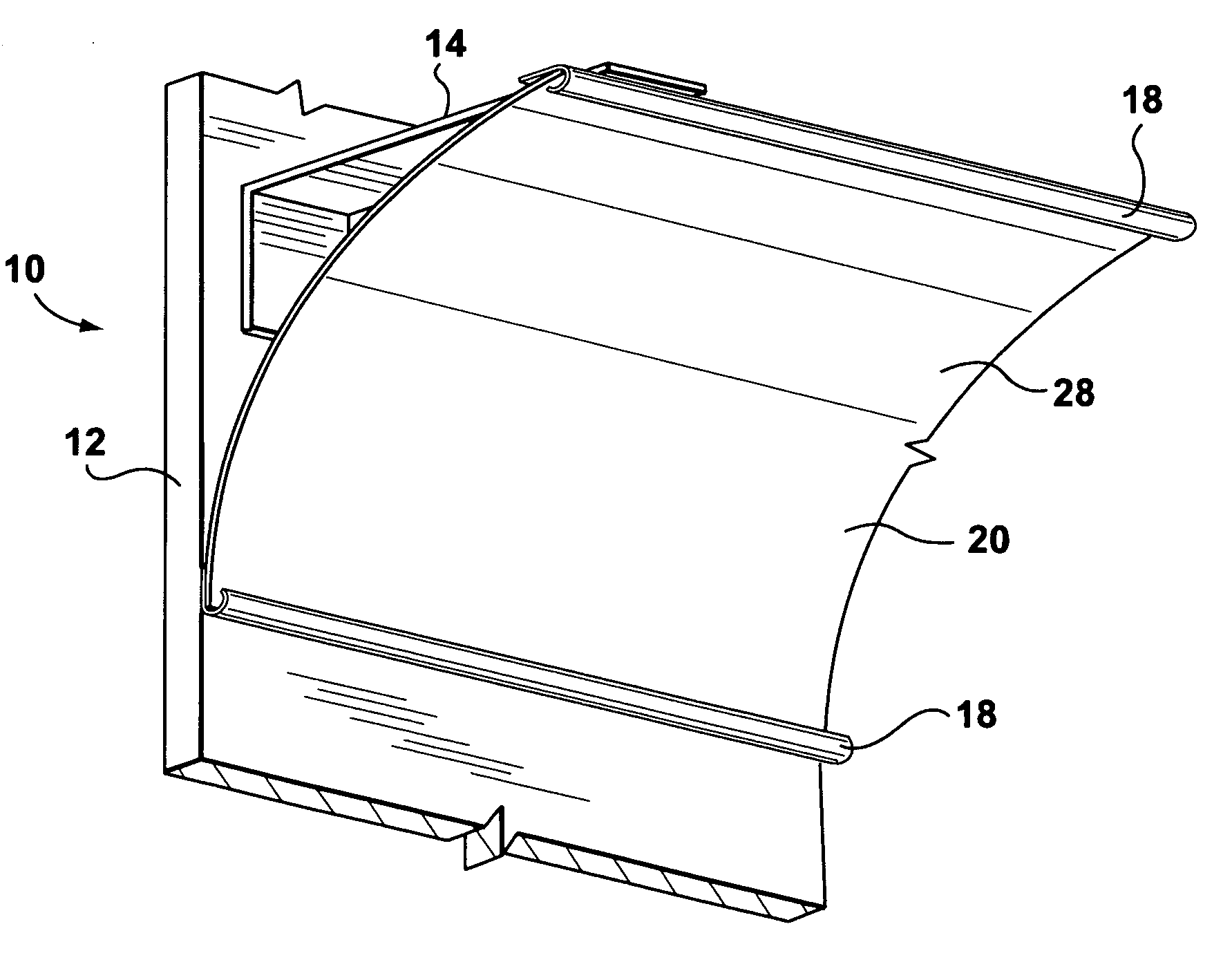
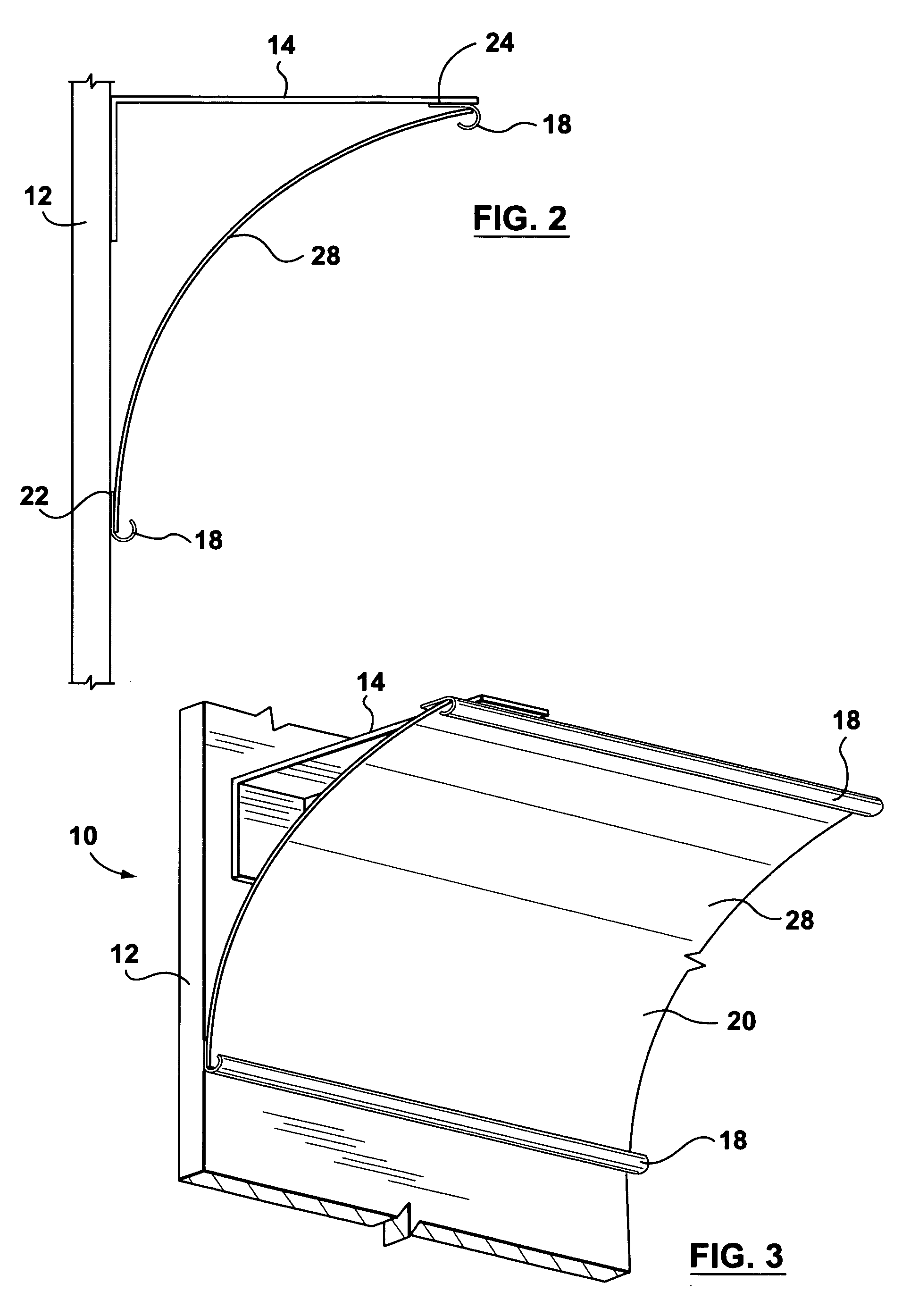
[0011] An object of one aspect of the present invention is to provide an improved beam signage and communication system that allows for improved visibility of signage while allowing customized displays that can include product samples and graphics, which are easy to construct and manipulate.
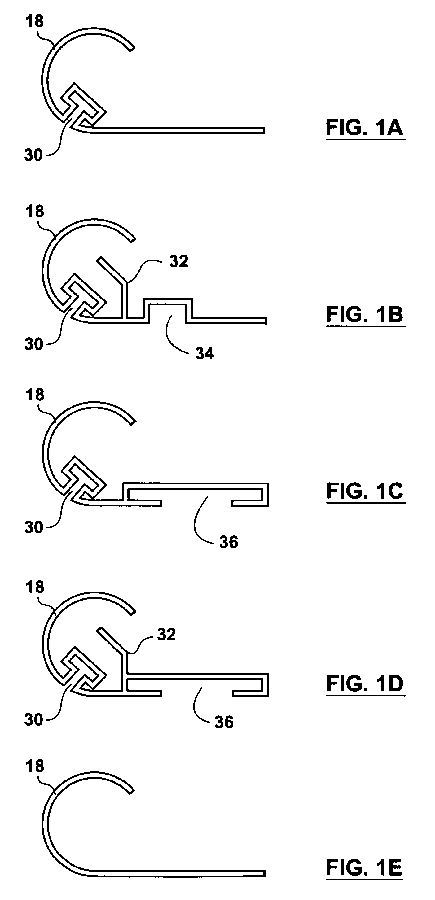
[0013] Preferably the changeable communication means is at least one flexible graphic having either a flat, a convex or a concave profile and has various attachment zones at different angles to accommodate a wide range of positioning to make viewing the communication system convenient and easy to read. Conveniently the positioning channels may have a variety of different profiles to accommodate creating different beam signage and communication systems. By using a system of extruded shapes the instant invention can accommodate a wide range of graphics or samples in various positions above, on and below the beams and shelves in a retail store.

Problems solved by technology

Inaccurate signage and the inability to locate the product in association with the signage can mean that the consumer will not bother purchasing the product and frustrating the consumer.
Product samples are often loosely displayed, easily removed or lost, or permanently attached to the displays, thereby making it more difficult to make changes to the display when the product assortment changes.
There are very few systems available, which allow the retailer to efficiently display product samples that are difficult to remove by the customer but are easy to change out when changes to the product assortment are required.
Similar problems are found with signage systems that include copy or graphics advertising the product.
Furthermore, many existing displays are permanently attached to the racking or display or storage (often sticking out in the aisle), making access to stock behind the sign impossible or difficult without damaging the display.
Many displays are also not durable or flexible enough to withstand harsh retail environments and thus sustain permanent damage from lift trucks, customers removing product, etc.
As a result, replacement costs for signage can often be high.
There has been limited development of large-scale display signage systems that adapt to various programs or store environments as well as changing graphics especially in the home improvement store environment.
A large portion of the existing display holders can not be easily modified at the store level to allow for increases or decreases in product assortment, or changing graphics.
Furthermore existing display holders often do not allow for the easy interchanging of graphics by the retailer and require the retailers to reprint the signage.
However, the prior art display devices do not address a beam signage and communication system that is easy to install, allows for lateral movement of graphics as well as easy removal of graphics in large scale for the home improvement store environment.
Most prior art display devices also only move between a hanging down position in which the signage is visible yet at an awkward angle and a locked up position in which the signage is not visible.
Moreover, the prior art devices only allow for the display of signage and not product samples, are difficult to manipulate and can not be customized to create a wide variety of signage display systems.

Method used


Image

  • Beam signage and communication system
  • Beam signage and communication system
  • Beam signage and communication system

Examples


Embodiment Construction

[0030] Referring to FIGS. 1-9 there is illustrated a beam signage and communication system 10 for a display or storage structure 12 in accordance with a preferred embodiment of the present invention. The beam signage and communication system 10 for a display or storage structure 12 includes a least one bracket 14 shaped to the display or storage structure 12 that has attachment zones 16, at least two positioning channels 18 and a changeable communication means 20. The attachment zones 16 may be angled 16, along a vertical 22 or a horizontal 24. The brackets 14 may be mounted to the display or storage structure 12 a variety of ways including traditional fastening mechanisms.

[0031] The beam signage and communication system 10 may further include at least two positioning channels 18 that may be spaced apart and are parallel to one another. The two positioning channels 18 may be mounted to the bracket 14 at the angled attachment zones 16, the vertical attachment zones 22 or the horizon...


PUM


Abstract

A beam signage and communication system for a display or storage structure, which includes a bracket shaped to the display or storage structure that may have attachment zones. The attachment zones may be angled to allow for improved visibility. The beam signage and communication system may further include at least two positioning channels that may be spaced apart and are parallel to one another. The two positioning channel may be mounted to the bracket at the angled attachment zones. The beam signage and communication system may also include a changeable communication means supported between the two positioning channels only by the weight of the changeable communication means thereby allowing the changeable communication means to be viewed at an angle.

Description

FIELD OF THE INVENTION [0001] This invention relates in general to a system for displaying signs and more particularly to a beam signage and communication system having enhanced graphic flexibility and is mounted on display or storage structures and has a variety of configurations. BACKGROUND OF THE INVENTION [0002] Signage and / or point of purchase displays are used throughout the retail business to ensure consumer awareness of a product. A wide variety of signage is available, such as active signs, which have moving display cases, animation and static signs which are the most common as they mount to some portion of a shelf or rack and are relatively economical. The proper display or storage of the relevant product in close proximity to the signage is crucial to ensure that the consumer is first of all aware of the product and secondly to encourage the consumer to purchase the product. Inaccurate signage and the inability to locate the product in association with the signage can mea...

Claims


Application Information

Patent Timeline
Patent Type & Authority Applications(United States)
IPC IPC(8): G09F3/20
CPCG09F1/00G09F15/0025
Inventor GRANT, DEAN
Owner STRATH ELGIN
Learn More