Optical disk and method of integrating a high gain RFID antenna

a high-gain, optical disk technology, applied in the direction of mechanical recording, burglar alarm mechanical actuation, instruments, etc., can solve the problems of not being able to place rfid readers in close proximity to most, if not all, of the physical media, and disrupting the delicate dynamic balance needed, so as to achieve the effect of easy incorporation into the optical disk

Inactive Publication Date: 2006-04-06
MICROSOFT TECH LICENSING LLC
View PDF7 Cites 92 Cited by
  • Summary
  • Abstract
  • Description
  • Claims
  • Application Information

AI Technical Summary

Benefits of technology

[0010] In accordance with a first aspect of the present inventions, an optical disk comprises a disk substrate having a hub and a metallicized annular data layer radially extending outward from the hub. In one embodiment, the disk substrate comprises an optically transparent base material, such as polycarbonate, so that the data layer can be optically read through the substrate. The optical disk further comprises a radio frequency identification (RFID) transponder affixed to the disk substrate, e.g., on the non-data carrying hub of the disk substrate. In one embodiment, the RFID transponder comprises a small integrated circuit (IC) chip, so that it can be more easily incorporated into the optical disk. The RFID transponder may also be passive, thereby obviating the need for a battery. To prevent tampering, the RFID transponder may be at least partially embedded into the disk substrate, so that removal of the RFID transponder from the disk substrate would, in effect, destroy the optical disk, and thus any value that it would have to its unlawful owner.

Problems solved by technology

Thus, when scanning each pallet of optical disks, an RFID reader typically cannot be placed in close proximity to most, if not all, of the physical media.
The use of a battery on an optical disk, however, is not recommended for several reasons.
First, the additional weight of the battery will tend to disrupt the delicate dynamic balance needed to rotate optical disks within disk drives at high speeds—typically at thousands of revolutions a minute.
Second, batteries tend to leak their contents over time, resulting in damage to the optical disk, specifically the reflective surface.
Third, batteries have a limited life, and thus, the efficacy of the RF transponder chip will be lost over time.
Although this would not necessarily cause problems for royalty and supply chain tracking, which presumably would be accomplished before the end of battery life, any anti-counterfeiting functionality of the RF transponder chip would be lost once the battery was expired.
The option of coupling a high gain antenna to the RF transponder chip creates additional challenges.
Unlike with other applications, such as tracking aircraft, where the space available for incorporating a relative large antenna is virtually unlimited, the space available on an optical disk is severely limited—not only by the limited total area of the optical disk, but also by desire not to adversely affect the data storage region of the optical disk (i.e., the concentric region of the disk from which data is optically read).
However, this solution avails a nefarious person the opportunity of circumventing the anti-counterfeiting features of the RFID technology simply by peeling the label and accompanying RFID transponder off of the optical disk.
Further, there is an ever-present risk that that the label substrate adhesive can, in some cases, transfer to the drive clamping mechanism, thereby potentially risking damage to the optical reader.

Method used


Image

  • Optical disk and method of integrating a high gain RFID antenna
  • Optical disk and method of integrating a high gain RFID antenna
  • Optical disk and method of integrating a high gain RFID antenna

Examples


Embodiment Construction

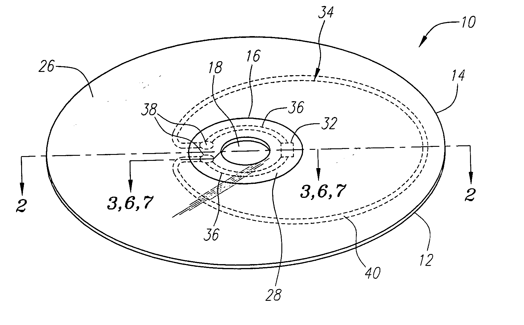
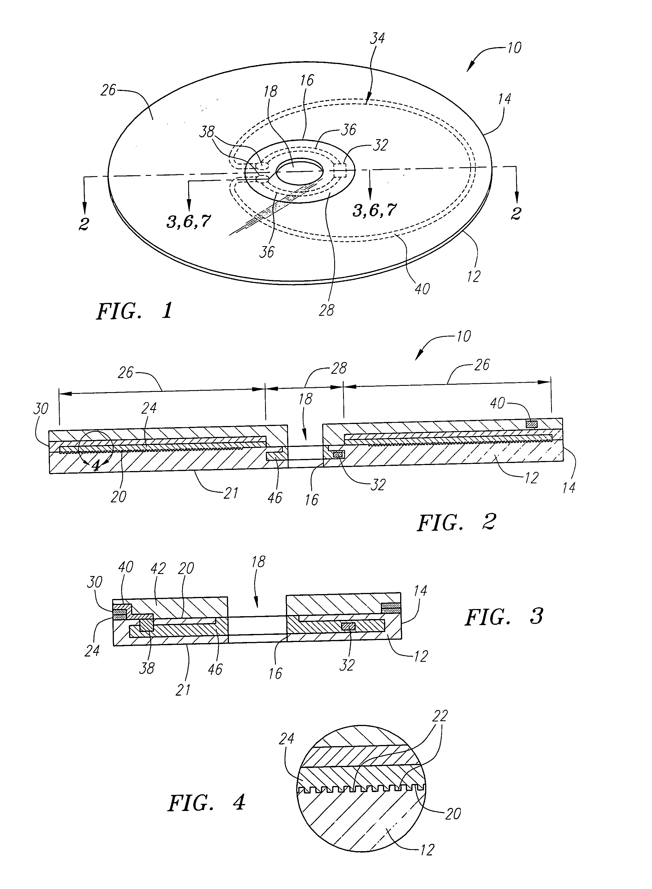
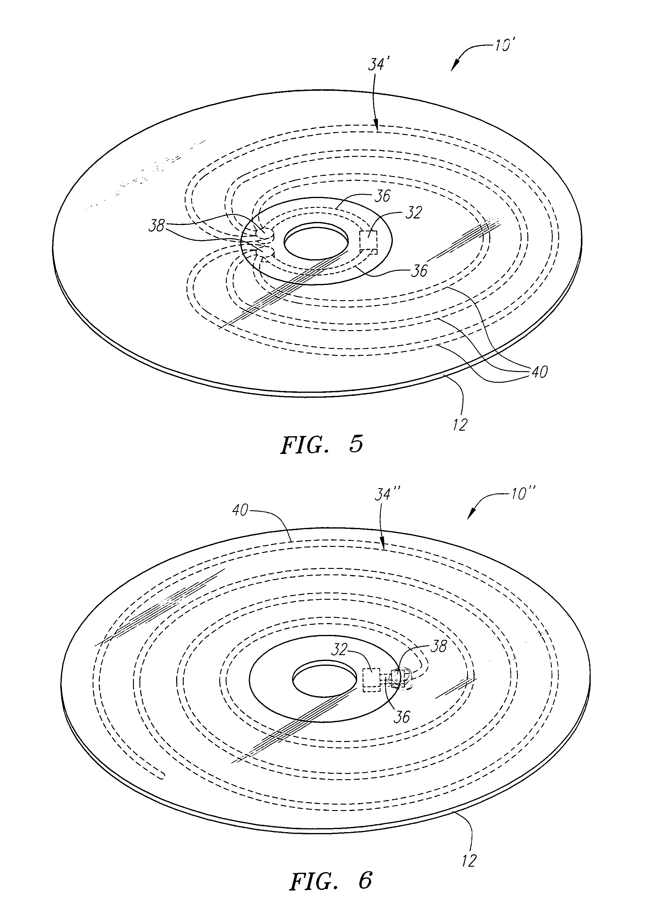
[0033] Preferred embodiments of optical disks constructed in accordance with the present inventions will now be described. The optical disks described herein carry radio frequency identification (RFID) technology that can be easily and cheaply incorporated into standard optical disk fabrication processes and is capable of working at a range of a few millimeters, e.g., to prevent counterfeiting of the optical disks when detected by an radio frequency (RF) reader contained within an optical disk driver, or at a range of several feet, e.g., for tracking purposes during the supply of packaged optical discs. For the purposes of this discussion, an optical disk refers to any disk that carries a data region that can be optically read, such as any of the Compact Disk (CD) family of optical disks, including, but not limited to, CD-ROM, CD-R, and the like, as well as the Digital Video Disk (DVD) family of optical disks, including, but not limited to, DVD-ROM, DVD-R, and the like. Currently, t...


PUM


Abstract

An optical disk comprises a disk substrate having a hub and an annular optical metallicized data region extending radially outward from the hub. The optical disk further comprises a radio frequency identification (RFID) transponder affixed to the disk substrate, e.g., within the non-data containing hub region. The optical disk further comprises at least one linear antenna element coupled to the transponder, e.g., via pole lead(s), and extending within the data region. The antenna element(s) can be applied to the disk substrate as a patterned antenna layer over a metallicized data region, and can be electrically isolated from the data region. A method and system of identifying an optical disk is provided. A radio frequency (RF) signal can be transmitted to the optical disk at a range of at least five feet, and preferably at a range of at least ten feet. An RF signal with an identification code (e.g., a unique number) can be received from the optical disk in response to the transmitted RF signal. The activating RF signal can be transmitted by, and the identification RF signal can be received by, e.g., a handheld RF reader or an RF reader that is affixed to a building. The identification code can then be processed for many purposes, such as identifying the optical disk as a non-counterfeited optical disk, calculating a royalty, or tracking the location of the optical disk.

Description

FIELD OF THE INVENTION [0001] The present invention relates generally to optical storage media and, in particular, to optical disks with embedded tracking devices and methods of integrating such tracking devices into optical disks. BACKGROUND OF THE INVENTION [0002] Radio frequency identification (RFID) technology is currently used for providing wireless automated identification of various devices. An RFID system generally includes a transponder called a “tag,” which is carried by the device to be identified, and an radio frequency (RF) tag reader, which communicates with the transponder. In particular, the RF transponder, in response to a wireless interrogation signal transmitted by the RF tag reader via an antenna, wirelessly transmits an identification code back to the RF tag reader, which decodes the code and sends it onto a host processor or computer for identification of the device. RF transponders may either be passive, semi-passive, or active. Passive transponders parasitica...

Claims


Application Information

Patent Timeline
Patent Type & Authority Applications(United States)
IPC IPC(8): G08B13/14
CPCG06K19/04G06K19/045G11B23/0042G06K19/042
Inventor BENEDIKT, MARK
Owner MICROSOFT TECH LICENSING LLC
Why Eureka
Try Eureka