Low cost electrical power connectivity for railway systems manufactured from conductive loaded resin-based materials

a technology of conductive resin and low cost, applied in the field of railway systems, can solve the problems of increasing electrical resistance, power loss, maintenance costs, and metal wires, and achieve the effect of effective electrical power connectivity

Inactive Publication Date: 2006-04-06
INTEGRAL TECHNOLOGY INC
View PDF3 Cites 40 Cited by
  • Summary
  • Abstract
  • Description
  • Claims
  • Application Information

AI Technical Summary

Problems solved by technology

First, metal wires, rails, and contact devices are susceptible to oxidation and other corrosion due to exposure to weather or due to electrolytic events.
This oxidation and corrosion structurally weakens these devices and substantially increases electrical resistance, power loss, and maintenance costs.
Second, the weight of metal wires, rails, and contact devices create several concerns.
Heavy overhead wires require heavy support poles that increase railway construction costs.
Similarly, heavy metal conductive rails require heavier support bridges and overpasses.
Heavy contact devices, such as metal pantographs and shoes, directly increase the weight of the train and result in reduced energy efficiency and / or slower operating speeds.

Method used


Image

  • Low cost electrical power connectivity for railway systems manufactured from conductive loaded resin-based materials
  • Low cost electrical power connectivity for railway systems manufactured from conductive loaded resin-based materials
  • Low cost electrical power connectivity for railway systems manufactured from conductive loaded resin-based materials

Examples


embodiment 250

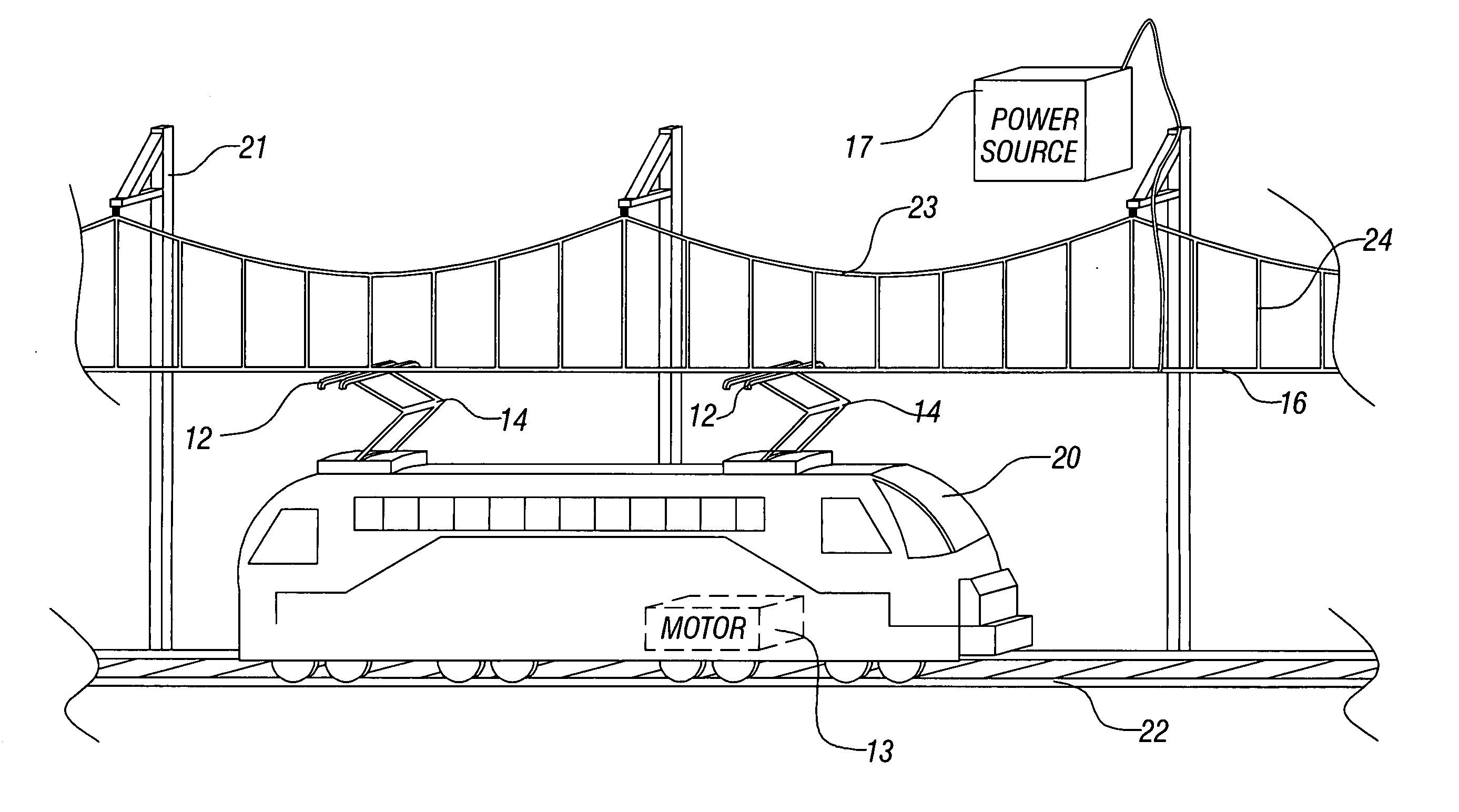
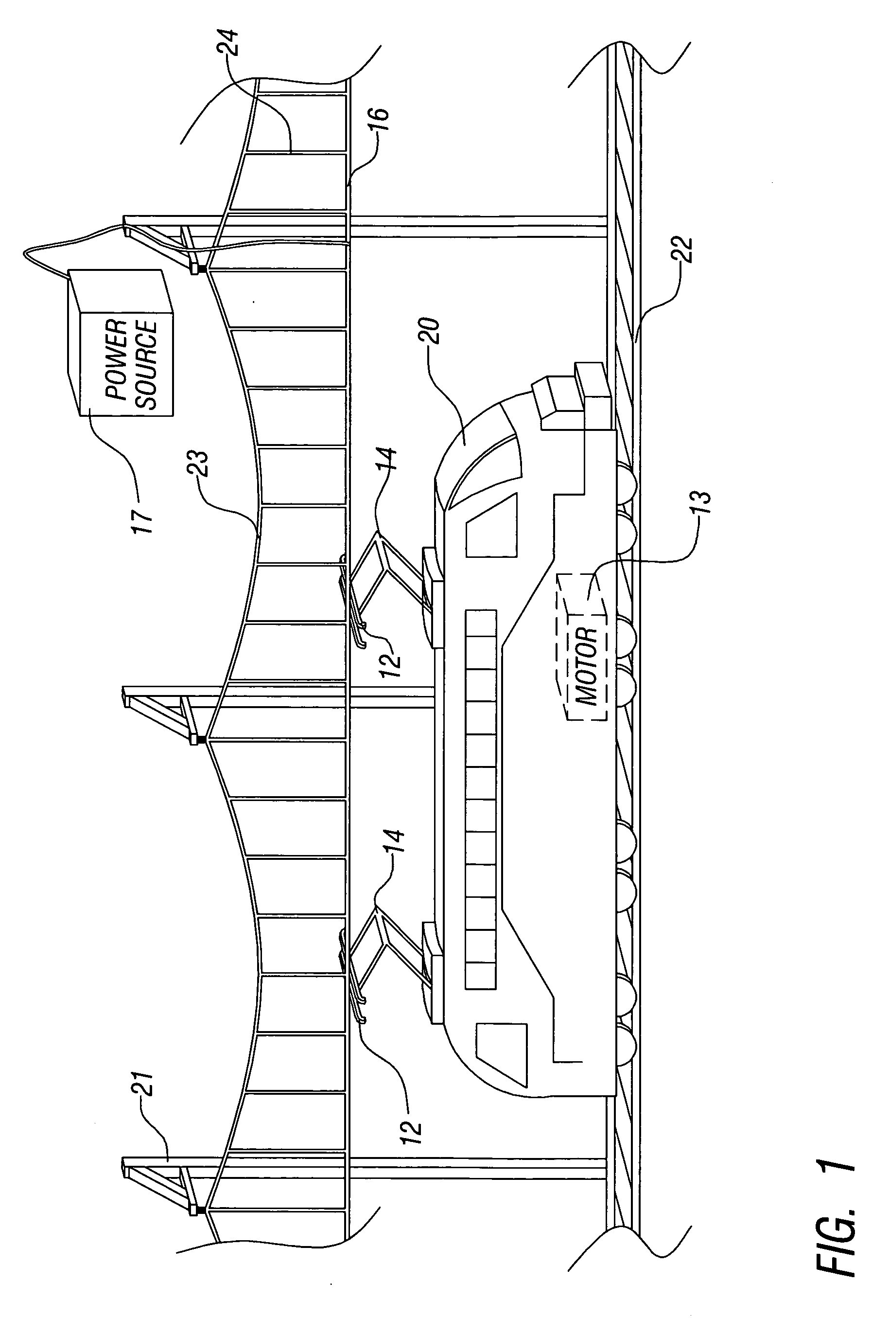
[0063] Referring now to FIG. 12, a seventh preferred embodiment of the present invention is illustrated. An embodiment 250 of a catenary contact wire 254 and dropper wire 258 coupling is illustrated in cross section. As described above, the contact wire 254 is used to conduct the operating current for an overhead power system as shown in FIG. 1. The dropper wire 258 is used to connect the contact wire 254 to the catenary structure. Referring again to FIG. 12, the dropper wire 258 is connected to the contact wire 254, according to this embodiment, by a connecting clamp 262. According to this embodiment, any, or all, of the contact wire 254, the dropper wire 258, and the clamp 262 comprise the conductive loaded resin-based material of the present invention.

[0064] Referring again to FIG. 1, by forming various electrical contacting structures, such as the pantograph 12 and 14 and the catenary system 23, 24, and 16, from the conductive loaded resin-based material of the present invention...

embodiment 200

[0069] Referring now to FIG. 11, an embodiment 200 of a fourth rail power system is illustrated. In a 4th rail system, positive and negative connections are provided for the power supply. By comparison, in the third rail system shown in FIGS. 9 and 10, the running rails 142 are used as ground return lines for the electrical current, whether DC or AC. Referring again to FIG. 11, two power rails 210 and 214 are provided along with the running rails 206 and sleepers 204. The power rails 210 and 214 allow for positive and negative DC terminals, such as +300 Volts and −300 Volts, to be used in the power system. In addition, the running rails 206 are not used as ground returns thus improving performance. The electrical rails 210 and 214 are again separated from the sleeper 204 by insulators 208. Separate shoes 212 and 216 are used to couple each rail 210 and 216 to the train. FIGS. 9 through 11 illustrate 3rd and 4th rail systems where the shoe contacts the rail on the top rail surface. T...


PUM

PropertyMeasurementUnit
diametersaaaaaaaaaa
diametersaaaaaaaaaa
diametersaaaaaaaaaa

Abstract

Electrical connectivity devices for railway systems are formed of a conductive loaded resin-based material. The conductive loaded resin-based material comprises micron conductive powder(s), conductive fiber(s), or a combination of conductive powder and conductive fibers in a base resin host. The percentage by weight of the conductive powder(s), conductive fiber(s), or a combination thereof is between about 20% and 50% of the weight of the conductive loaded resin-based material. The micron conductive powders are metals or conductive non-metals or metal plated non-metals. The micron conductive fibers may be metal fiber or metal plated fiber. Further, the metal plated fiber may be formed by plating metal onto a metal fiber or by plating metal onto a non-metal fiber. Any platable fiber may be used as the core for a non-metal fiber. Superconductor metals may also be used as micron conductive fibers and / or as metal plating onto fibers in the present invention.

Description

RELATED PATENT APPLICATIONS [0001] This Patent Application claims priority to the U.S. Provisional Patent Application 60 / 629,261 filed on Nov. 19. 2005, which is herein incorporated by reference in its entirety. [0002] This Patent Application is a Continuation-in-Part of INT01-002CIPC, filed as U.S. patent application Ser. No. 10 / 877,092, filed on Jun. 25, 2004, which is a Continuation of INT01-002CIP, filed as U.S. patent application Ser. 10 / 309,429, filed on Dec. 4, 2002, now issued as U.S. Pat. No. 6,870,516, also incorporated by reference in its entirety, which is a Continuation-in-Part application of docket number INT01-002, filed as U.S. patent application Ser. No. 10 / 075,778, filed on Feb. 14, 2002, now issued as U.S. Pat. No. 6,741,221, which claimed priority to U.S. Provisional Patent Applications Ser. No. 60 / 317,808, filed on Sep. 7, 2001, Ser. No. 60 / 269,414, filed on Feb. 16, 2001, and Ser. No. 60 / 268,822, filed on Feb. 15, 2001, all of which are incorporated by referenc...

Claims


Application Information

Patent Timeline
Patent Type & Authority Applications(United States)
IPC IPC(8): H01Q9/04
CPCB29C45/0013H01B1/22H01B1/24H01H1/027H01H1/029H01H1/065H01H1/38
Inventor AISENBREY, THOMAS
Owner INTEGRAL TECHNOLOGY INC
Why Eureka
Try Eureka