Heat conduction unit with improved laminar

Inactive Publication Date: 2010-02-11
LEE CHAN BONG
View PDF8 Cites 28 Cited by
  • Summary
  • Abstract
  • Description
  • Claims
  • Application Information

AI Technical Summary

Benefits of technology

[0024]The heat conduction unit of the present invention is manufactured using a laminar implemented with a composite material of a high water absorbent fabric and a coated resin having a high moisture permeability and air shield ability, thereby improving the heat and moisture exchange performance with enhanced moisture permeability and water repellent effect while avoiding the contamination controversy caused by the reinforcement and absorbent materials used in the fabrication of conventional heat conductive unit.
[0025]Also, the heat conduction unit of the present invention is advantageous in product reliability and durability since the laminar of the heat conduction unit has improve

Problems solved by technology

Accordingly, the conventional laminar fabrication is carried out through complicated additional processes including reinforcement process and absorbent agent application process in addition to the basic shaping process, and these additional processes cause a environment contamination problems due to the toxicity of the additive materials.
Also, the conventional laminar is likely to have a low porosity due to the use of large amount of reinforcement agent, even though it may be compensated by the absorbance agent, which restricts the efficient moisture exchange performance of the

Method used


Image

  • Heat conduction unit with improved laminar
  • Heat conduction unit with improved laminar
  • Heat conduction unit with improved laminar

Examples


Embodiment Construction

[0032]Exemplary embodiments of the present invention are described with reference to the accompanying drawings in detail. The same reference numbers are used throughout the drawings to refer to the same or like parts. Detailed descriptions of well-known functions and structures incorporated herein may be omitted to avoid obscuring the subject matter of the present invention.

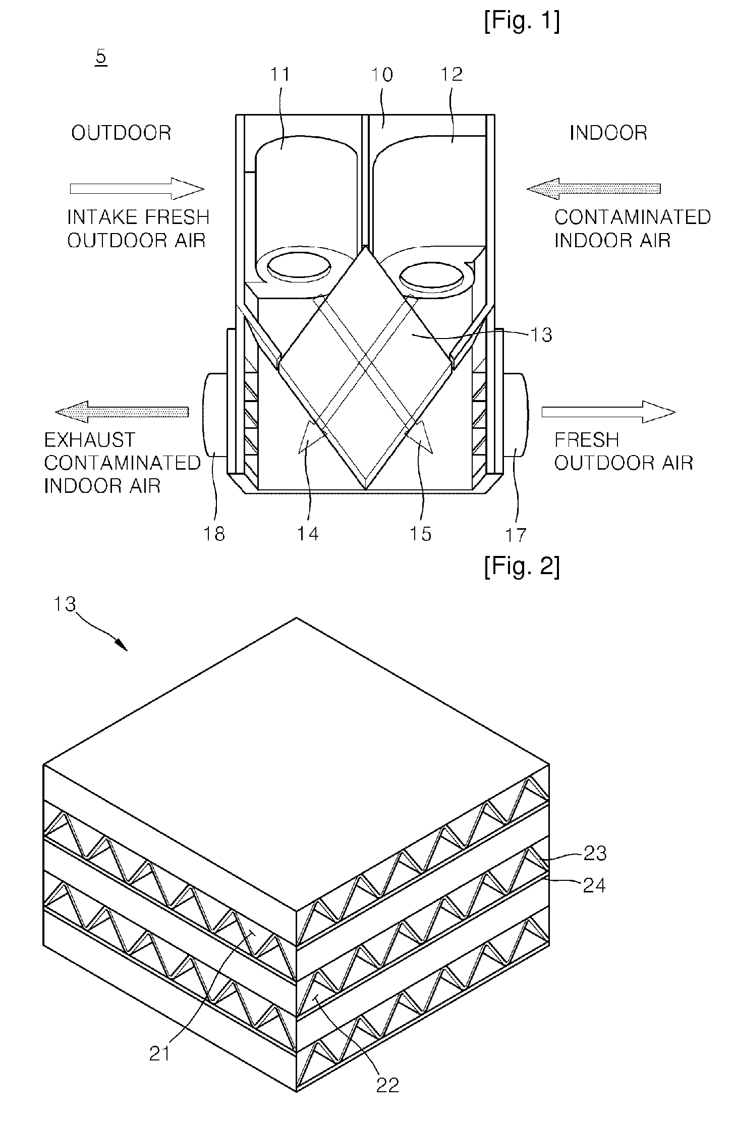
[0033]FIG. 1 is a top plan view illustrating a heat exchanger according to an exemplary embodiment of the present invention. Referring to FIG. 1, the heat exchanger 5 includes a housing 10 having a box shape and a pair of exhaust and intake passages 16 and 17 for guiding exhaust and intake airflows 14 and 15, respectively.

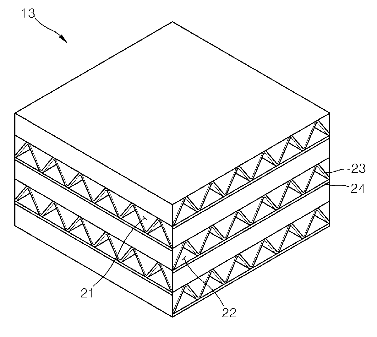
[0034]The heat exchanger 5 further includes a heat conduction unit 13 arranged at a portion at which the exhaust and intake passages 16 and 17 are crossing each other for exchanging heats between the exhaust and intake airflows 14 and 15, and a pair of exhaust and intake fans 12 and 11.

[0035]If ...


PUM

PropertyMeasurementUnit
Temperatureaaaaaaaaaa
Electrical conductivityaaaaaaaaaa
Permeabilityaaaaaaaaaa

Abstract

A heat conduction unit having an improved laminar is provided. The heat conduction unit of the present invention includes a pair of exhaust and intake layers crossing each other for exchanging heat between exhaust and intake airflows; and a laminar interposed between the exhaust and intake layers and having a having a fiber synthetic fabric layer with a high water absorbancy and heat conductivity. The fiber synthetic fabric layer is made by densely weaving a microfiber in the form of a fabric, the fabric being weaved by adding micro metal fiber, by adding microfiber plated with metal, or by adding at least ones of micro copper molecules, aluminum molecules, carbon black molecules, carbon nano tube molecules, titanium dioxide (TiO2) molecules, and nano-silver molecules, to a raw material resin of the microfiber.

Description

TECHNICAL FIELD[0001]The present invention relates to a heat conduction unit that is capable of improving thermal conductivity and performance reliability.BACKGROUND ART[0002]A heat exchanger is a device for preventing the indoor temperature from changing abruptly and maintaining the indoor humidity using sensible and latent heat exchanges during air ventilation. Such heat exchanger is provided with exhaust and intake passages crossing each other, exhaust and intake fans for generating the exhaust and intake airflows through the respective exhaust and intake passages, and a heat conduction unit arranged at the crossing part of the exhaust and intake passage for heat and moisture exchanges between the exhaust and intake airflows.[0003]Korean Patent Laid-Open Publication No. 2003-004007 discloses a heat conduction element. The conventional heat conduction element is provided with basic components each of which is formed by laminating a laminar having a flat shape and a spacer having a...

Claims


Application Information

Patent Timeline
IPC IPC(8): F28F13/18
CPCF24F3/147F24F12/006Y02B30/563F28D21/0015F28F21/065F28D9/0062Y02B30/56A23B9/08B01D45/14
Inventor LEE, CHAN BONG
Owner LEE CHAN BONG
Why Eureka
Try Eureka