
High frequency energy application to petroleum feed processing

a technology of petroleum feed and high frequency energy, applied in the direction of hydrocarbon oil treatment, hydrocarbon preparation, hydrocarbon oil cracking process, etc., can solve the problems of catalyst deactivation, catalytic material loss, catalytic material deterioration due to abrasion, etc., and achieve the effect of reducing the formation of coke on the catalys

Inactive Publication Date: 2006-04-06
BURKITBAYEV SERIK M
View PDF9 Cites 10 Cited by
  • Summary
  • Abstract
  • Description
  • Claims
  • Application Information

AI Technical Summary

Problems solved by technology

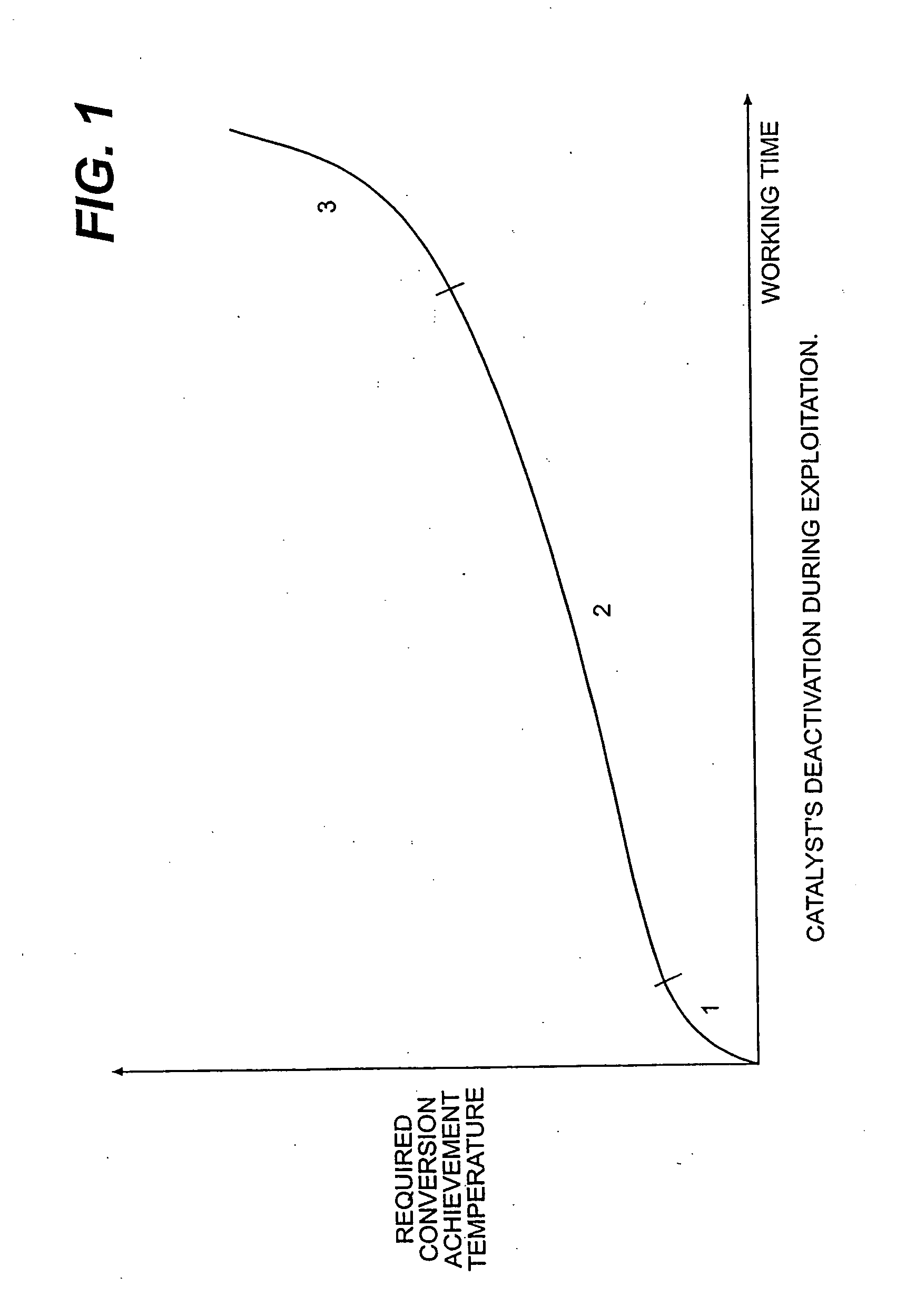
In all oil processes using catalysts, deactivation of the catalyst occurs due to poisoning of catalysts and due to coke formation on the catalyst.
The precipitation of heavy metals, such as nickel, vanadium, iron, can also result in the deactivation of the catalyst.
With traditional methods for regenerating the catalyst there is the loss of catalytic material, deterioration due to abrasion, and loss in activity.
However, these systems typically utilize a plasma initiator in the reactor resulting in more complicated hydroprocessing systems.
This emulsion is very expensive to separate.

Method used


Image

  • High frequency energy application to petroleum feed processing
  • High frequency energy application to petroleum feed processing
  • High frequency energy application to petroleum feed processing

Examples


Embodiment Construction

[0026] All oil processes that use catalysts are complicated by catalyst deactivation. The deactivation is typically due to poisoning the catalyst with sulfur and due to coke precipitation on the catalyst. Further, the precipitation of heavy metals such as nickel, vanadium, and iron results in catalyst deactivation. The accumulation of coke catalyst requires regeneration of the catalyst. In cyclic operating plants, the catalyst must be periodically regenerated and in plants with a moving catalyst layer, the catalyst must be continuously regenerated. Some procedures require the plant to shut down so the catalyst may be unloaded from the reactor followed by catalyst regeneration. Some systems have a cyclic system where the catalyst is transferred from the reactor to a regeneration column followed by the transfer of the catalyst to the reactor without shutting down the system. The regeneration column operates at high temperatures and requires additional power and cost to operate. When t...


PUM

PropertyMeasurementUnit
frequencyaaaaaaaaaa
frequencyaaaaaaaaaa
pressureaaaaaaaaaa

Abstract

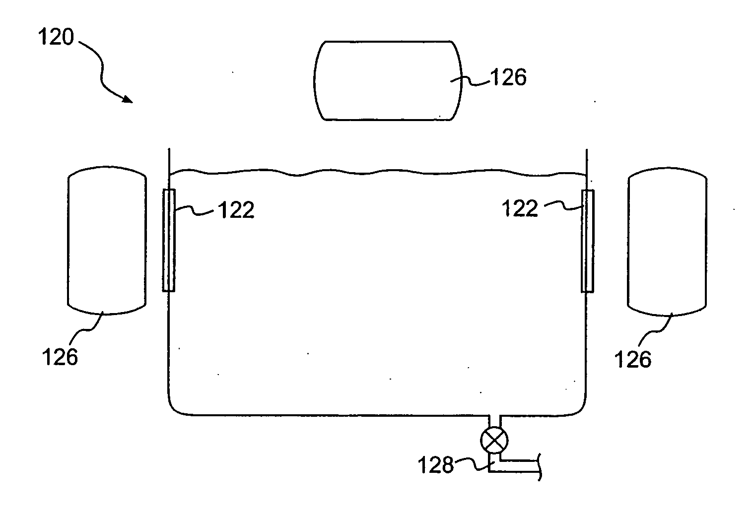
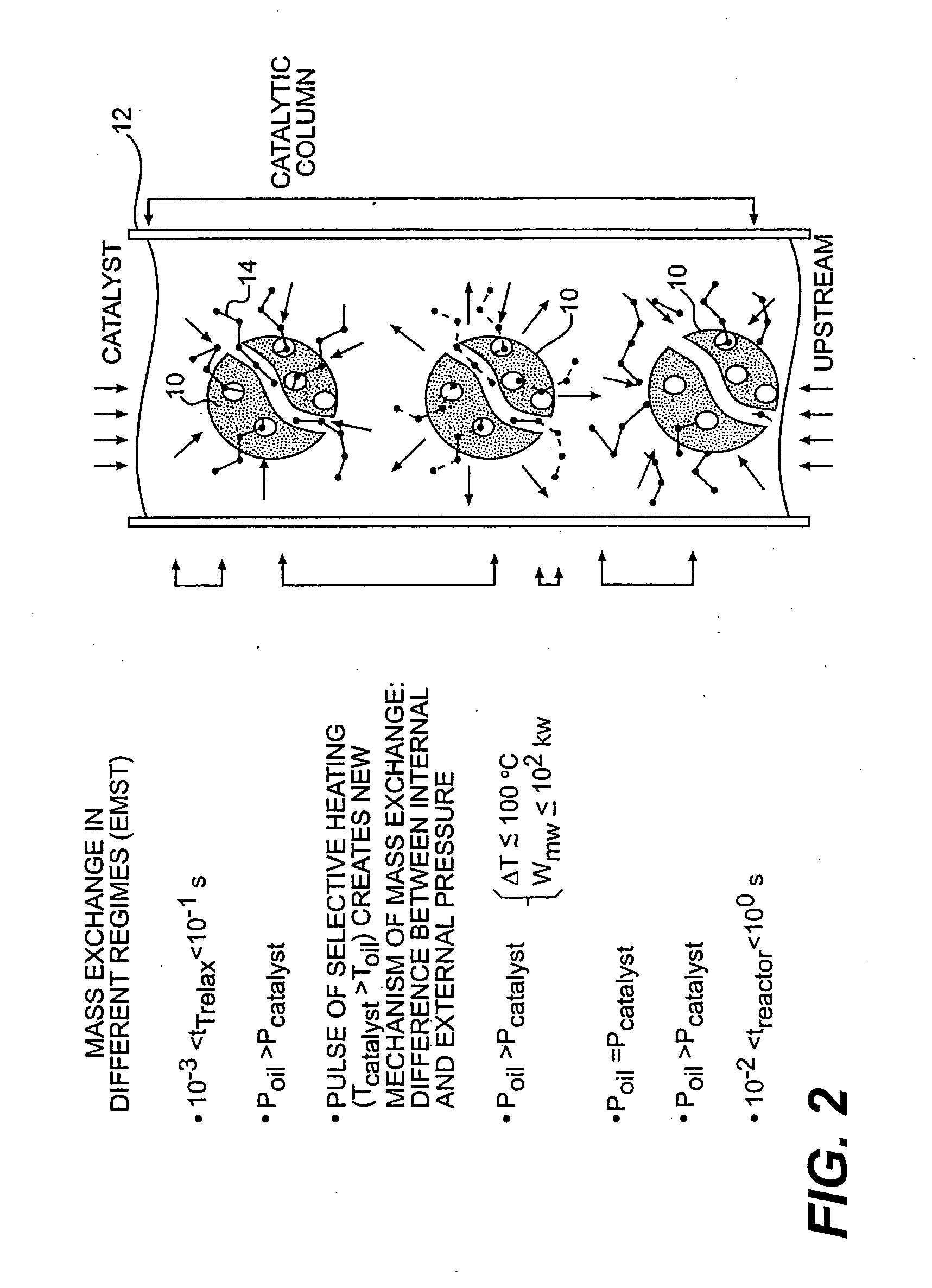
The present invention provides a method and apparatus for maintaining the active life of a catalyst in organic feed processing by applying a series of electromagnetic radiation pulses to the catalyst in a reactor. The pulsing of the catalyst selectively heats and cools the catalyst and can regulate the relative internal pressure of the catalyst particles to stimulate the acceleration of oil macromolecules mass-exchange through the catalyst pores and surface. This allows for the removal of cracked oil molecules from the particles. The application of electromagnetic pulses also regulates the activity of the catalyst. The electromagnetic radiation reduces the formation of coke on the catalyst and increases the life of the catalyst in the reactor. Further, the present invention provides a method and apparatus for removing water and salt from an organic feed. Water and salt is removed by applying a series of electromagnetic radiation pulses to the organic feed. A first pulse condenses water contained in the feed and induces salt to dissolve in the condensed water. A second pulse vaporizes a portion of the condensed water droplets to bring the droplets to the surface of the organic feed.

Description

CROSS-REFERENCE TO RELATED APPLICATIONS [0001] This is a divisional application of co-pending U.S. application Ser. No. 10 / 243,681, filed Sep. 16, 2002, which is a divisional application of U.S. application Ser. No. 09 / 709,307, filed Nov. 13, 2000, now U.S. Pat. No. 6,451,174, of which benefit and priority is claimed hereby under 35 U.S.C. § 120 and the disclosure of which are expressly incorporated by reference in their entirety.FIELD OF THE INVENTION [0002] The present invention relates broadly to a method and apparatus for exposing a processing catalyst to high frequency energy in the presence of an organic feed such as a hydrocarbon feed. Further, the invention is directed to pulsing high frequency energy to remove water and salt from organic feeds such as petroleum feeds. BACKGROUND OF THE INVENTION [0003] In all oil processes using catalysts, deactivation of the catalyst occurs due to poisoning of catalysts and due to coke formation on the catalyst. The precipitation of heavy ...

Claims


Application Information

Patent Timeline
Patent Type & Authority Applications(United States)
IPC IPC(8): C07C1/00B01J19/08B01J8/20B01J8/42B01J19/00B01J19/12C10G15/08C10G32/02
CPCB01J8/20B01J8/42B01J19/0026B01J19/12B01J19/121B01J19/126B01J19/128B01J2208/00707B01J2219/0854B01J2219/0877B01J2219/0892B01J2219/1227C10G15/08C10G32/02C10G49/02C10G2300/703Y10S44/904Y10S44/905
Inventor BURKITBAYEV, SERIK M.
Owner BURKITBAYEV SERIK M
Learn More