Tag location,client location, and coverage hole location in a wireless network

a wireless network and client location technology, applied in the field of wireless networks, can solve the problems of increasing the cost of stations, e.g., client devices, and not including field calibration to correct ap measurements, and achieve the effect of low power consumption

Inactive Publication Date: 2006-04-06
CISCO TECH INC
View PDF87 Cites 209 Cited by
  • Summary
  • Abstract
  • Description
  • Claims
  • Application Information

AI Technical Summary

Benefits of technology

[0028] One aspect of the invention is providing a common infrastructure for radio tags and client stations of a WLAN to be located using radiolocation by path loss measurement. Another aspect of the invention is defining a mechanism for radio tags to transmit information with relatively low power consumption compared to transmitting normal payload carrying frames. A frame format is defined that according to one embodiment of the invention provides an extremely efficient method for conveying all the information needed to locate radio tags and clients using path loss measurements.
[0029] Another aspect of the invention provides for interoperability of tags and clients from various vendors. By using the frame format defined herein, any radio tag or client may be efficiently located. For example, in one application, radio tags from a first company, and client stations made by a second company, may be located by a location server made by the second, or by an unrelated third company.

Problems solved by technology

GPS, however, is known to have poor indoor reception and long acquisition time.
GPS also requires additional GPS hardware in the wireless station that would increase the cost of stations, e.g., client devices.
Furthermore, the Moore et al. method is described for client stations only and not as a unified method suitable for tag location, WLAN coverage area gap determining, and client station location.
Furthermore, the Moore et al. method does not include any field calibration to correct AP measurements by using AP to AP path loss measurement.
Known methods of radiolocation using signal strength measurements may be unsuitable for tag location because of the requirements for tags to have long battery life and automated operation.

Method used


Image

  • Tag location,client location, and coverage hole location in a wireless network
  • Tag location,client location, and coverage hole location in a wireless network
  • Tag location,client location, and coverage hole location in a wireless network

Examples


Embodiment Construction

[0056] One embodiment of the present invention is a method of determining the likely location or locations of a radio tag or client station, or determining the location of a gap (also called a hole) in WLAN coverage.

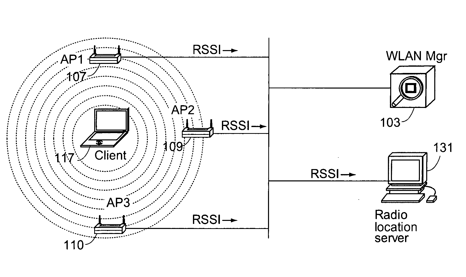
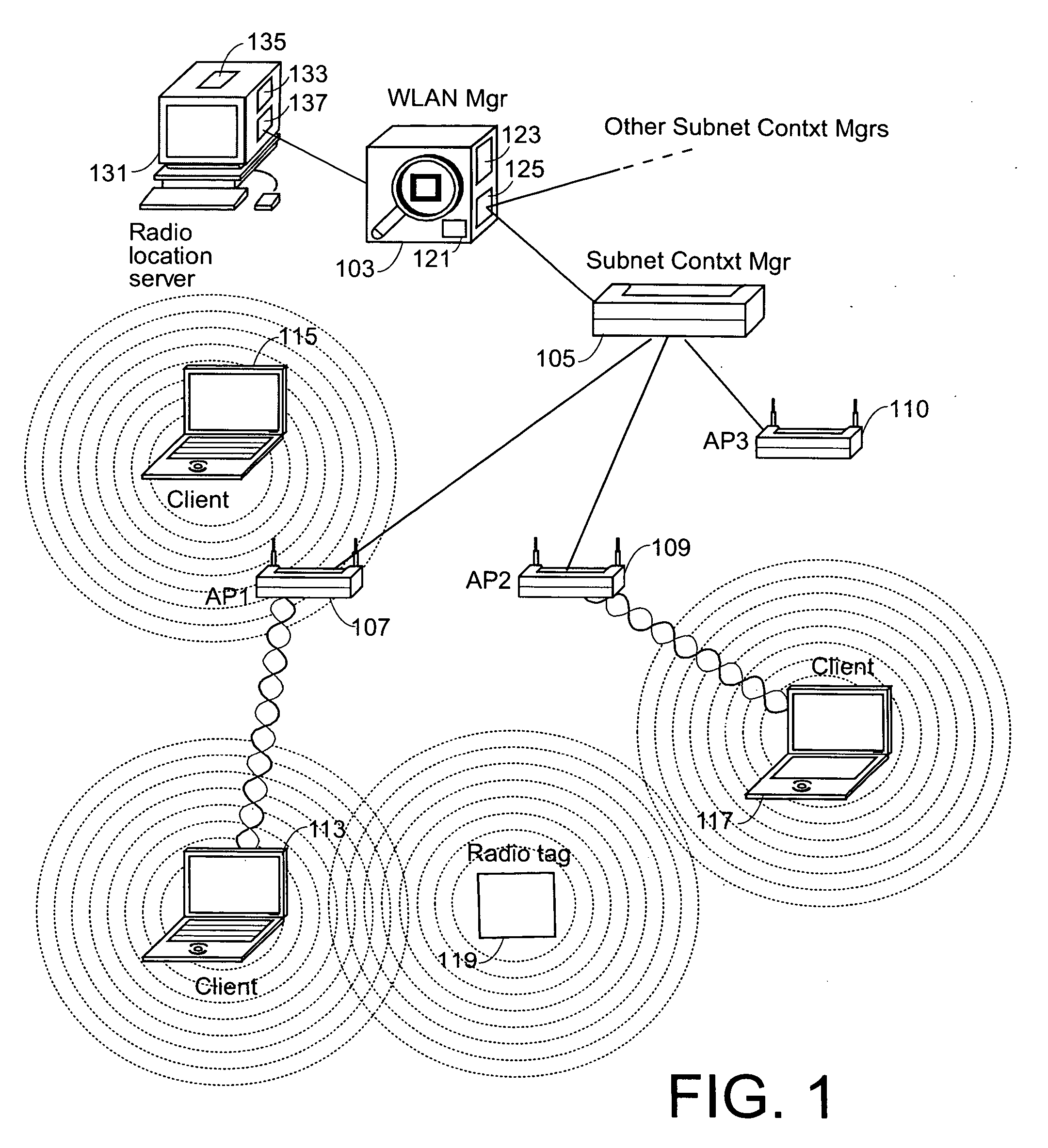
[0057] One aspect of the invention includes defining a common frame having pre-defined frame structure to be used by transmitting radio tags and by client stations transmitting to a pre-assigned multicast address. Such a frame is called a location frame, and also a path loss measurement frame herein. In the remainder of the description, it is assumed that the to-be-located radio tags and the client stations are “conforming” in that they transmit such a location frame. It is also assumed that access points also are “conforming” in that they listen at the pre-defined multicast address, and understand the pre-defined frame structure of a location frame. In one embodiment, the conforming APs are assumed to be managed APs in a managed WLAN as described in above-mentioned and...


PUM


Abstract

Determining the location of a radio tag or client station of a wireless network, and the location of coverage holes by receiving from a plurality of wireless stations of the wireless network path loss information of the path loss of one or more location frames received at the respective wireless stations. The location frames transmitted by the radio tag or client station having a pre-defined frame structure. The radio tags and client stations use a common infrastructure for transmitting a location frame configured for radiolocation by path loss measurement. The common infrastructure includes a pre-defined protocol common for both radio tags and client stations for transmitting information for reception by the plurality of stations of the wireless network for radiolocation. The pre-defined protocol includes using the location frame having the pre-defined frame structure.

Description

RELATED CASES [0001] The present invention claims priority of U.S. Provisional Patent Application Ser. No. 60 / 649,721 filed Feb. 3, 2005 to inventors Douglas et al., titled TAG LOCATION, CLIENT LOCATION, AND COVERAGE HOLE LOCATION IN A WIRELESS NETWORK, and assigned to the assignee of the present invention. The contents of U.S. Provisional Patent Application Ser. No. 60 / 649,721 are incorporated herein by reference. [0002] The present invention also claims priority of, and is a continuation-in-part of U.S. patent application Ser. No. 10 / 629,384 filed Jul. 28, 2003 to inventors Kaiser et al., titled RADIOLOCATION USING PATH LOSS DATA, and assigned the the assignee of the present invention. Such U.S. patent application Ser. No. 10 / 629,384 is referred to herein as the Kaiser et al. invention, and the contents of this application are incorporated herein by reference.BACKGROUND [0003] The present invention relates to wireless networks, and in particular to a method and system for locating...

Claims


Application Information

Patent Timeline
Patent Type & Authority Applications(United States)
IPC IPC(8): G06F15/16H04W28/04H04W48/08H04W48/16H04W64/00
CPCG01S5/0252H04W28/04H04W48/08H04W48/16H04W64/00H04W80/00
Inventor DOUGLAS, BRETTON LEEOLSON, TIMOTHY S.HALASZ, DAVID E.DENG, JOHN Z.BILSTAD, ARNOLD M.YANG, SHEAUSONGREBO, RICHARD D.LEARY, JONATHAN S.KAISER, DARYL A.
Owner CISCO TECH INC
Why Eureka
Try Eureka