Nozzle and filter-type dust collector

a technology of dust collector and nozzle, which is applied in the direction of machine/engine, process and machine control, and fluid pressure control, etc., can solve the problems of increasing the risk of a drop in dust-collection efficiency, affecting the efficiency of dust collection, so as to save running costs, reduce the amount of fluid to be supplied, and high efficiency

Inactive Publication Date: 2006-04-13
TAKUMA
View PDF14 Cites 24 Cited by
  • Summary
  • Abstract
  • Description
  • Claims
  • Application Information

AI Technical Summary

Benefits of technology

[0019] According to this filter-type dust collector, since it is equipped with a nozzle having a Laval nozzle section and a fluid guide section with an elongated opening, a highly intensive supersonic stream of fluid accompanied with a shock wave can be directed against the filter member. Thus, shocks are given to the filter member by the shock wave so that removal of highly-adhesive, extraneous matter from the surface of the filter member can be ensured. In addition, since extraneous matter can be removed with high efficiency, the amount of fluid to be supplied can be reduced, thereby saving the running cost for the removal of extraneous matter. Further, since there is no need to increase fluid pressure unlike the prior art systems, the internal pressure of the filter-type dust collector is not abruptly increased by injection of the fluid, which enables it to eliminate the adverse effect on the dust collector.

Problems solved by technology

Known waste incineration systems have suffered from the drawback that dust generated in flue gas during burning of waste in an incinerator adheres to the inner wall surface of the exhaust gas duct etc.
Since the neglect of dust adhesion / deposition leads to problems such as blockage of the duct, many attempts have been made to remove dust.
If dust adheres to a filter member, in particular, in a filter-type dust collector for collecting dust from exhaust gas, there will arise increasing risks of a drop in dust-collection efficiency, a backflow of exhaust gas resulting from a rise in the internal pressure of the dust collector, and damage to the dust collector itself.
The gas filter system 100 which employs the above-described ceramic filters 105, however, cannot be expected to have such a whisking effect, not only because the system 100 is used for exhaust gas having high temperatures of 300 to 800° C. which causes strong dust adhesion, but also because of the rigidity of the ceramic filters 105.
Further, in the dust removal device 110 such as shown in FIG. 5, air jetted from the spouts 112 disperses in all directions before reaching the Venturi tubes 106, which makes it difficult to efficiently direct the jet air to the inside of the ceramic filters 105.

Method used


Image

  • Nozzle and filter-type dust collector
  • Nozzle and filter-type dust collector
  • Nozzle and filter-type dust collector

Examples


Embodiment Construction

[0025] Referring now to the accompanying drawings, a nozzle and a filter-type dust collector will be concretely described according to a preferred embodiment of the invention.

[0026] The present embodiment is associated with a gas filter system having ceramic filters as a filter member, which is a typical example of the filter-type dust collector.

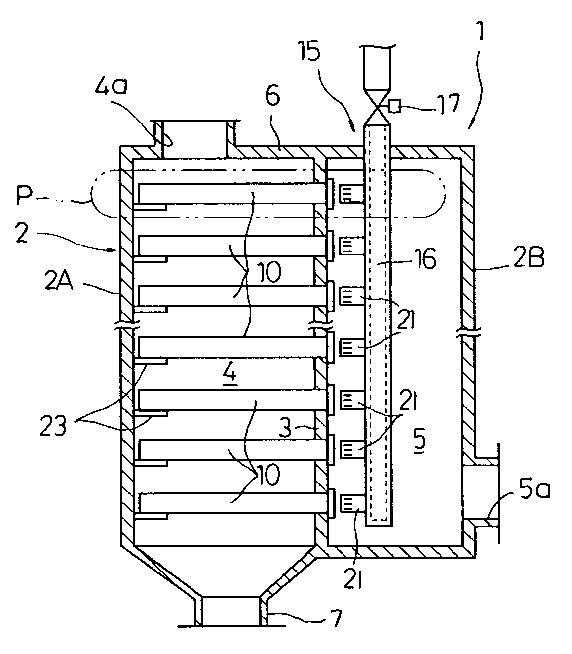
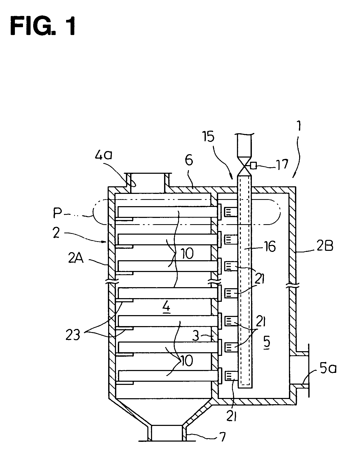
[0027]FIG. 1 is a schematic longitudinal sectional view of a gas filter system according to one embodiment of the invention. FIG. 2 is an expanded sectional view of a region P shown in FIG. 1. FIG. 3(a) is a sectional view of a nozzle and FIG. 3(b) is a sectional view taken along line A-A of FIG. 3(a).

[0028] As shown in FIG. 1, the gas filter system 1 of this embodiment is equipped with a prismatic casing 2 vertically arranged. This casing 2 includes a partition wall 3 which is vertically arranged so as to divide the inner space of the casing 2. The partition wall 3 is opposed to the opposite outer walls 2A, 2B of the casing 2. A gas intr...


PUM

PropertyMeasurementUnit
temperaturesaaaaaaaaaa
surface pressureaaaaaaaaaa

Abstract

There are provided a nozzle capable of enhancing the straight-advancing capability of jetted fluid to increase the back wash effect of a filter member, and a filter-type dust collector capable of effectively carrying out dust removal from a filter member with such a nozzle. To this end, the nozzle has a Laval nozzle section secured to the inside of an outer tube at its proximal end and a fluid guide section disposed at the leading end of the outer tube. The fluid guide section has a plurality of suction holes elongated in the flowing direction of the pressurized fluid. This nozzle is mounted on a pulse header tube of a dust removal device.

Description

TECHNICAL FIELD [0001] The invention relates to a nozzle for jetting a fluid and a filter-type dust collector using such a nozzle. BACKGROUND ART [0002] Known waste incineration systems have suffered from the drawback that dust generated in flue gas during burning of waste in an incinerator adheres to the inner wall surface of the exhaust gas duct etc. Since the neglect of dust adhesion / deposition leads to problems such as blockage of the duct, many attempts have been made to remove dust. [0003] If dust adheres to a filter member, in particular, in a filter-type dust collector for collecting dust from exhaust gas, there will arise increasing risks of a drop in dust-collection efficiency, a backflow of exhaust gas resulting from a rise in the internal pressure of the dust collector, and damage to the dust collector itself. For this reason, dust removal has been heretofore seriously considered. Typical filter-type dust collectors include bug filter systems which use, as a filter membe...

Claims


Application Information

Patent Timeline
Patent Type & Authority Applications(United States)
IPC IPC(8): B01D46/04
CPCB01D46/0068B01D46/0069B01D46/2407B01D2277/30Y10T137/0536Y10T137/2322B01D46/715B01D46/71
Inventor YOSHIMOTO, SATOSHI
Owner TAKUMA
Why Eureka
Try Eureka