Microfluidic substrates having improved fluidic channels

a microfluidic substrate and fluid channel technology, applied in the direction of basic electric elements, electrical appliances, printing, etc., to achieve the effect of reducing the wettability of side wall surfaces, and reducing the surface energy of side wall surfaces

Active Publication Date: 2006-04-13
FUNAI ELECTRIC CO LTD
View PDF1 Cites 30 Cited by
  • Summary
  • Abstract
  • Description
  • Claims
  • Application Information

AI Technical Summary

Benefits of technology

[0009] An advantage of the invention is that fluid flow, particularly ink flow, through narrow channels in a micro-fluid ejecting device is significantly improved. Without desiring to be bound by theory, it is believed that a passivating or etch stop layer coating formed during a reactive ion etching process for making fluid flow channels in a silicon substrate lowers the surface energy of side wall surfaces of the fluid flow channels. The lower surface energy reduces the wettability of the side wall surfaces relative to the fluid flowing through the channels. As the wettability of the side wall surfaces decreases, the resistance to fluid flow through the channels is increased. Increased fluid flow resistance may contribute to reduced fluid flow to ejection chambers on a substrate for the micro-fluid ejecting device. Under high frequency operation, misfiring of the ejection device may result if the ejection chambers are not adequately refilled between fluid ejection cycles. By increasing the surface energy of the fluid flow channels, the invention improves fluid flow through the channels.
[0010] Additionally, fluid flow channels having relatively low surface energy are more likely to attract and hold air bubbles which can impede fluid flow through the channels. While not desiring to be bound by theory, it is believed that the invention reduces the accumulation of air bubbles in the fluid flow channels by increasing the surface energy of the fluid flow channels.

Problems solved by technology

Under high frequency operation, misfiring of the ejection device may result if the ejection chambers are not adequately refilled between fluid ejection cycles.

Method used


Image

  • Microfluidic substrates having improved fluidic channels
  • Microfluidic substrates having improved fluidic channels
  • Microfluidic substrates having improved fluidic channels

Examples


Embodiment Construction

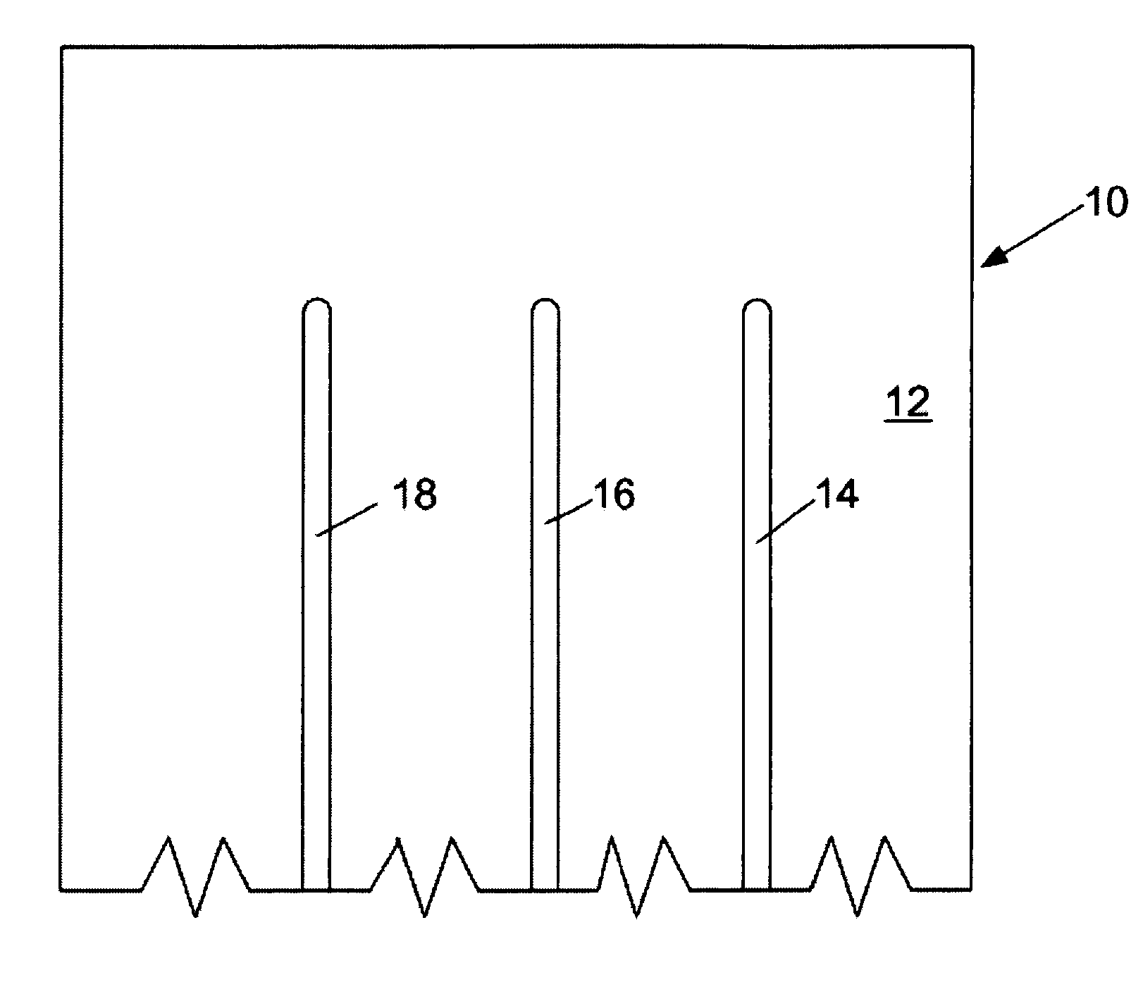
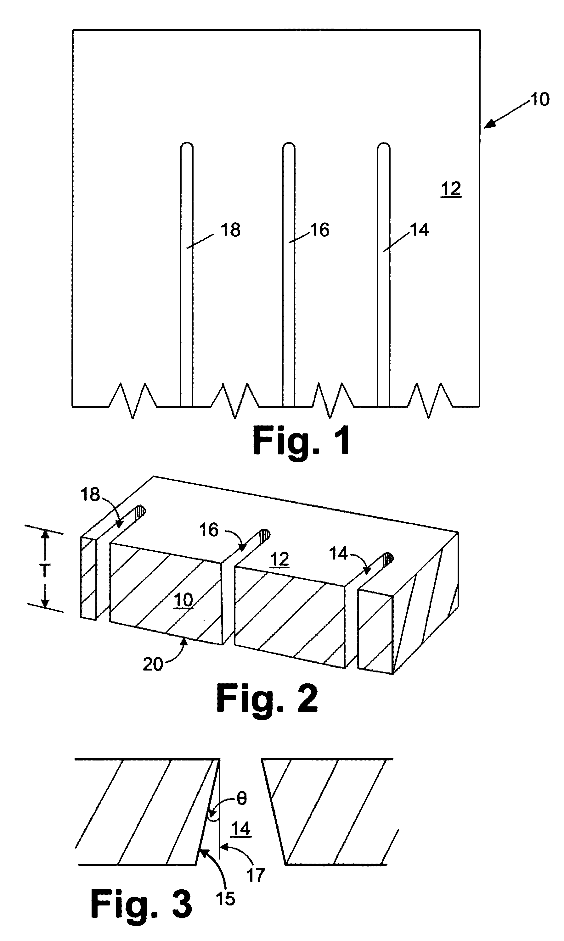
[0020] With reference to FIGS. 1 and 2, the invention provides a semiconductor silicon chip 10 for a micro-fluid ejecting device such as an ink jet printhead, having a device surface 12 and containing a plurality of openings or fluid feed slots 14, 16, and 18 therein. The semiconductor chip 10 is relatively small in size and typically has overall dimensions ranging from about 2 to about 10 millimeters wide by about 10 to about 36 millimeters long. A primary aspect of the invention relates to the dimensions and manufacturing process for the fluid feed slots 14, 16, and 18 through the chip 10.

[0021] In conventional semiconductor chips for ink jet printheads, slot-type ink feed ports are grit blasted in the chips. Such grit blasted ink via slots generally have dimensions of about 9.7 millimeters long and 0.39 millimeters wide. Accordingly, the conventional chips must have a width sufficient to contain the relative wide ink via while considering manufacturing tolerances, and sufficient...


PUM


Abstract

A method for improving fluidic flow for a microfluidic device having a through hole or slot therein. The method includes the steps of forming one or more openings through at least part of a thickness of a substrate from a first surface to an opposite second surface using a reactive ion etching process whereby an etch stop layer is applied to side wall surfaces in the one or more openings during alternating etching and passivating steps as the openings are etched through at least a portion of the substrate. Substantially all of the etch stop layer coating is removed from the side wall surfaces by treating the side wall surfaces using a method selected from chemical treatment and mechanical treatment, whereby a surface energy of the treated side wall surfaces is increased relative to a surface energy of the side wall surfaces containing the etch stop layer coating.

Description

FIELD OF THE INVENTION [0001] The invention is directed to micro-fluid ejecting devices and more specifically to structures and methods for improving fluid flow through openings in substrates for the micro-fluid ejecting devices. BACKGROUND [0002] Micro-fluid ejecting devices such as ink jet printers continue to be improved as the technology for making the printheads continues to advance. New techniques are constantly being developed to provide low cost, highly reliable printers which approach the speed and quality of laser printers. [0003] One area of improvement in the printers is in the print engine or printhead itself. This seemingly simple device is a microscopic marvel containing electrical circuits, fluid passageways and a variety of tiny parts assembled with precision to provide a powerful, yet versatile component of the printer. The printhead components must also cooperate with an endless variety of ink formulations to provide the desired print properties. Accordingly, it i...

Claims


Application Information

Patent Timeline
Patent Type & Authority Applications(United States)
IPC IPC(8): B41J2/015B41J2/14B41J2/16
CPCB41J2/14145B41J2/1603B41J2/1623B41J2/1646B41J2/1631B41J2/1632B41J2/1645B41J2/1628
Inventor VAIDEESWARAN, KARTHIKMCNEES, ANDREW L.KRAWCZYK, JOHN W.MRVOS, JAMES M.HAMMOND, CORY N.DOERRE, MARK L.VANDERPOOL, JASON T.PATIL, GIRISH S.MONEY, CHRISTOPHER J.WILLIAMS, GARY R.WARNER, RICHARD L.
Owner FUNAI ELECTRIC CO LTD
Why Eureka
Try Eureka