
Clock generator and data recovery circuit using the same

a clock generator and data recovery technology, applied in pulse automatic control, digital transmission, angle demodulation by phase difference detection, etc., can solve the problem of longer tracking time and failure to timely reach the optimal sampling phase. , to achieve the effect of shortened tracking tim

Active Publication Date: 2006-04-13
REALTEK SEMICON CORP
View PDF1 Cites 55 Cited by
  • Summary
  • Abstract
  • Description
  • Claims
  • Application Information

AI Technical Summary

Benefits of technology

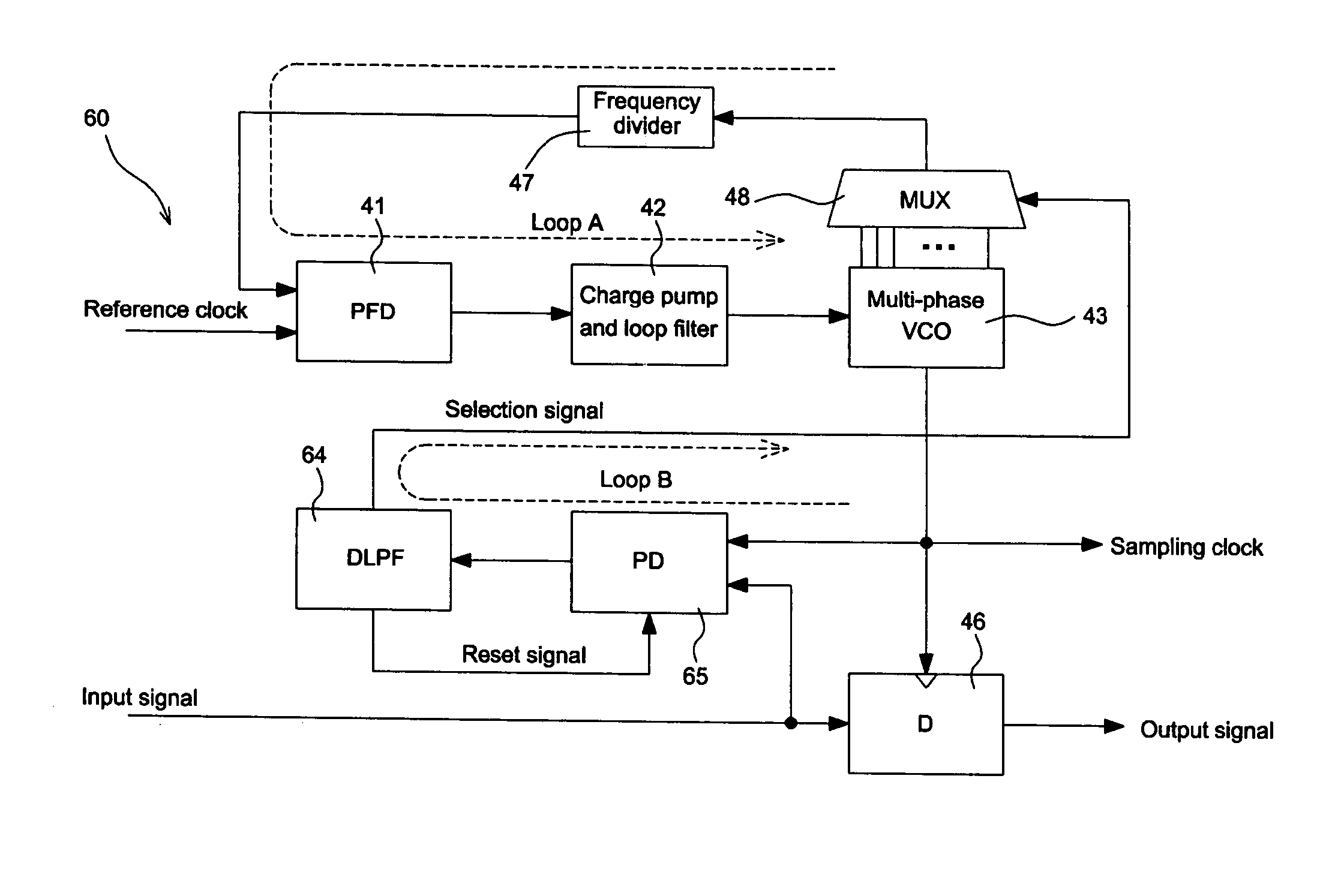
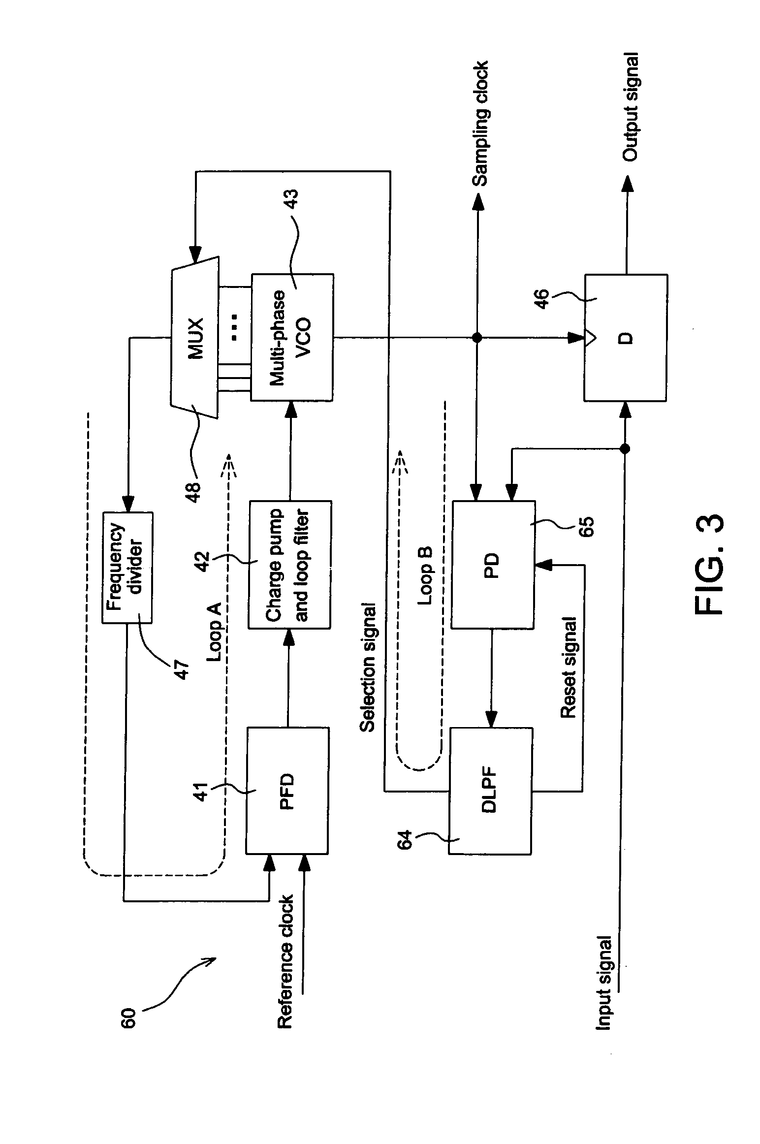
The invention is about a circuit that generates a sampling clock and a plurality of multi-phase clocks. It includes a voltage control oscillator, a multiplexer, a phase-frequency detector, a charge pump and loop filter, a phase detector, a digital low-pass filter, and a flip-flop. The circuit can select one of the multi-phase clocks to output based on a selection signal and can also clear an accumulated phase error. The invention also includes a data recovery circuit that includes a voltage controlled oscillation loop and a data recovery loop. The technical effects of the invention are that it can shorten the tracking time and improve data recovery accuracy.

Problems solved by technology

However, it has the drawback of failing to timely reach an optimal sampling phase longer tracking time for data recovery.

Method used


Image

  • Clock generator and data recovery circuit using the same
  • Clock generator and data recovery circuit using the same
  • Clock generator and data recovery circuit using the same

Examples


first embodiment

[0021]FIG. 3 shows a feedback-based data recovery circuit according to the invention. Referring to FIG. 3, the recovery circuit 60 includes a voltage controlled oscillation loop (loop A in FIG. 3), a data recovery loop (loop B in FIG. 3), and a D-type flip-flop 46. The voltage controlled oscillation loop includes a phase-frequency detector (PFD) 41, a charge pump and loop filter 42, a multi-phase voltage controlled oscillator (multi-phase VCO) 43, a multiplexer 48, and a frequency divider 47. The data recovery loop (loop B in FIG. 3) includes a digital low-pass filter (DLPF) 64 and a phase detector (PD) 65. The implementation and realization of each of the elements in FIG. 3 is well known to those of ordinary skill in the art, and is as described in Larsson. Detailed descriptions are therefore herein omitted.

[0022] The digital low-pass filter 64 of the recovery circuit 60 has the function of resetting and clearing the values temporarily stored in the phase detector 65. In addition t...

second embodiment

[0027]FIG. 5 shows a feedback-based data recovery circuit according to the invention. As shown in FIG. 5, the recovery circuit 80 is similar to the recovery circuit 60 of FIG. 3 except that a phase detector 45 does not have the reset function and a digital low-pass filter 84 does not output the reset signal.

[0028]FIG. 6 shows an embodiment digital low-pass filter design 84 of FIG. 5 using MATLAB code. In this embodiment, the signal “out” represents the selection signal, the parameter acc(n) represents the accumulated phase error, the parameter acctime(n) represents the accumulated time, the parameter N represents the phase adjustment amount in each adjustment, the parameter K represents the threshold phase difference, and the parameter Stoptime represents the stop accumulating time. As shown in FIG. 6, the program is divided into two parts. The first part 91 starts to accumulate the accumulated phase error acc(n) after the accumulated time acctime(n) exceeds the stop accumulating ti...


PUM


Abstract

A clock generator and a data recovery circuit. The clock generator includes a voltage control oscillator (VCO) for generating a sampling clock and multi-phase clocks, a multiplexer for receiving the multi-phase clocks and selecting one of the multi-phase clocks to generate a selected clock according to a selection signal, a phase-frequency detector for receiving the selected clock and a reference clock and generating a phase-frequency error signal, a charge pump and loop filter for receiving the phase-frequency error signal and generating a control voltage, a phase detector for receiving the sampling clock and an input signal and generating a phase error signal, and a digital low-pass filter for receiving the phase error signal and generating the selection signal. The digital low-pass filter clears an accumulated phase error when it generates the selection signal to force the multiplexer to change the phase.

Description

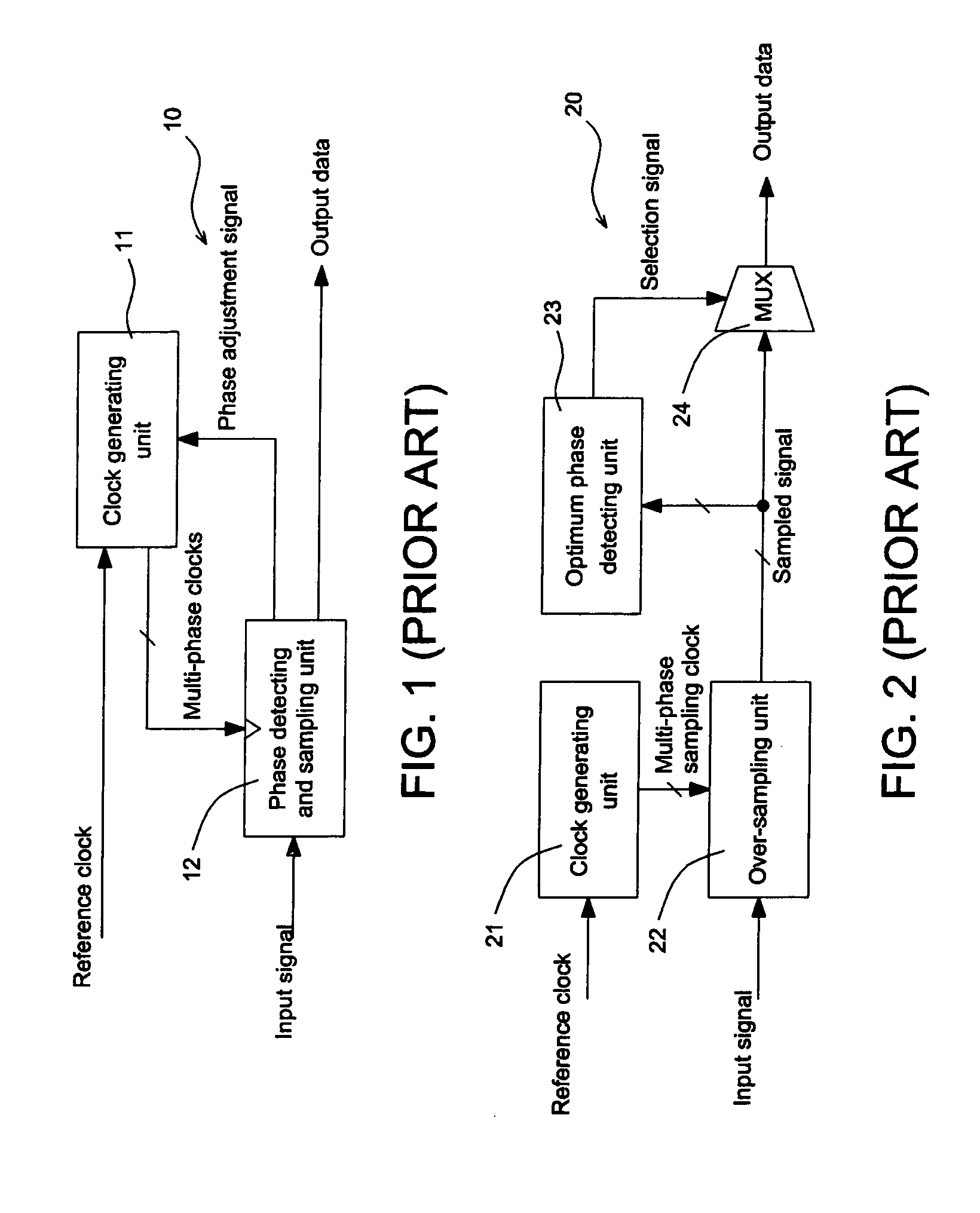
[0001] This application claims the benefit of the filing date of Taiwan Application Ser. No. 093130780, filed on Oct. 11, 2004, the content of which is incorporated herein by reference. BACKGROUND OF THE INVENTION [0002] 1. Field of the Invention [0003] The invention relates to clock generation, and more particularly, to a data recovery circuit with a clock generator. [0004] 2. Description of the Related Art [0005] In data interfaces of digital televisions, such as those of Digital Visual Interface (DVI) or of High-Definition Multimedia Interface (HDMI), data recovery circuits is generally used to recover data in a serial signal comprising the red (R), green (G), and blue (B) video data. Data recovery circuits typically can be categorized into feedback-based data recovery scheme or feedforward-based data recovery scheme. [0006]FIG. 1 shows the architecture of a feedback-based data recovery circuit. Referring to FIG. 1, the feedback-based data recovery circuit 10 includes a clock gen...

Claims


Application Information

Patent Timeline
Patent Type & Authority Applications(United States)
IPC IPC(8): H03D3/24H03L7/085H03L7/087H03L7/089H03L7/099H03L7/18H04L7/033
CPCH03L7/087H03L7/0891H03L7/0996H03L7/18H04L7/0338
Inventor LU, CHAO-HSIN
Owner REALTEK SEMICON CORP
Learn More