Hydraulic pressure control apparatus and method for continuously variable transmission

a technology of hydraulic pressure control and transmission line, which is applied in the direction of gearing control, gearing element, belt/chain/gearing, etc., can solve the problems of difficult to eliminate the problem of excessive overshooting of the line, and the time at which the command pressure is set to the maximum value is simply delayed

Active Publication Date: 2006-04-13
JATCO LTD +1
View PDF7 Cites 35 Cited by
  • Summary
  • Abstract
  • Description
  • Claims
  • Application Information

AI Technical Summary

Benefits of technology

[0003] However, in the above-described case, a time at which the command pressure is set to the maximum value is merely delayed. It is difficult to eliminate a problem of an excessive overshooting of the line pressure due to a stepwise rise in the command pressure.
[0004] It is, therefore, an object of the present invention to provide hydraulic pressure control apparatus and method for a continuously variable transmission of an automotive vehicle which are capable of suppressing the overshoot developed in the line pressure when the line pressure is raised to operate the continuously variable transmission when a shift range of the continuously variable transmission is switched from the N range to the D range.
[0007] According to a still another object of the present invention, there is provided with a hydraulic pressure control method for a continuously variable transmission, comprising: developing a line pressure of the continuously variable transmission with a working oil supplied from an oil pump as an original pressure; and setting a command pressure to develop a line pressure target value of the target value in such a manner that the command pressure is maintained at a predetermined small value for a constant time and, thereafter, the value of the command pressure is raised up to the target value when a shift range of the continuously variable transmission is switched from a neutral range to a running range, the command pressure being raised at a rate lower than a step input to suppress an overshoot developed in the actual line pressure.

Problems solved by technology

However, in the above-described case, a time at which the command pressure is set to the maximum value is merely delayed.
It is difficult to eliminate a problem of an excessive overshooting of the line pressure due to a stepwise rise in the command pressure.

Method used


Image

  • Hydraulic pressure control apparatus and method for continuously variable transmission
  • Hydraulic pressure control apparatus and method for continuously variable transmission
  • Hydraulic pressure control apparatus and method for continuously variable transmission

Examples


Embodiment Construction

[0016] Reference will hereinafter be made to the drawings in order to facilitate a better understanding of the present invention.

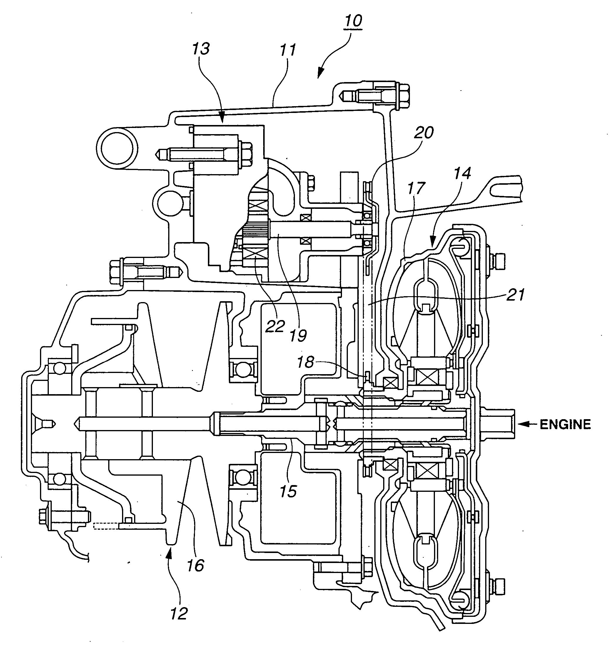
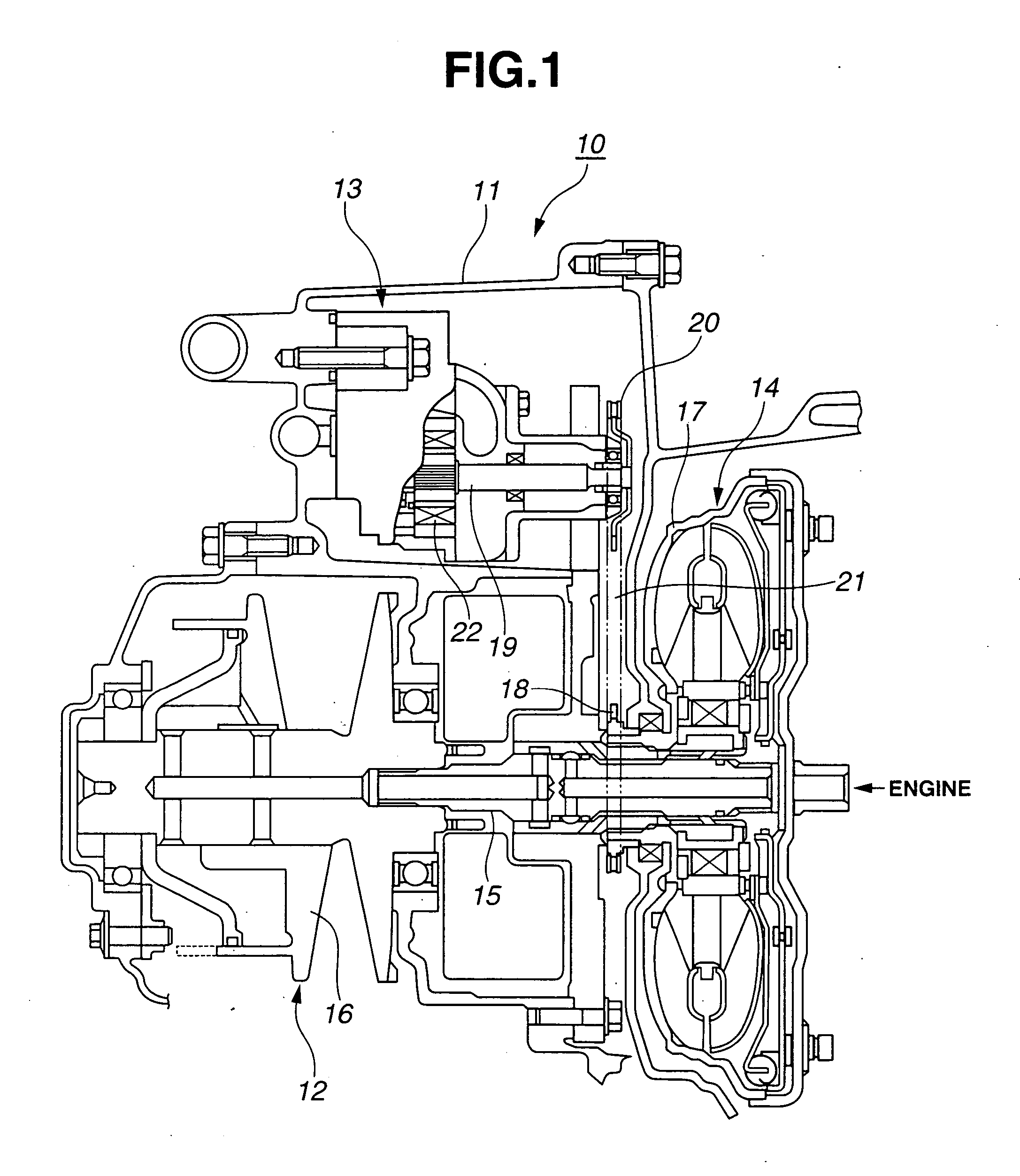
[0017]FIG. 1 shows a schematic cross sectional view of a continuously variable transmission to which a hydraulic pressure control apparatus according to the present invention is applicable. Continuously variable transmission 10 shown in FIG. 1 is also called a belt type continuously variable transmission. An oil pump 13 and a shift mechanism 12 are housed within a transmission casing 11. A revolution of an engine is transmitted from an input axle 15 via a torque converter 14 to a primary pulley 16. In this continuously variable transmission 10, a belt is bridged between a primary pulley 16 of shift mechanism 12 and a secondary pulley thereof. Pulley width of each of primary pulley 16 and the secondary pulley is varied so that a radius of the belt of each pulley is varied. Thus, a continuous shift operation is carried out. It is noted that torque converter...


PUM


Abstract

In hydraulic pressure control apparatus and method for a continuously variable transmission, a line pressure of the continuously variable transmission is developed with a working oil supplied from an oil pump as an original pressure, and a command pressure is set to develop a line pressure target value of the target value in such a manner that the command pressure is maintained at a predetermined small value for a constant time and, thereafter, the value of the command pressure is raised up to the target value when a shift range of the continuously variable transmission is switched from a neutral range to a running range, the command pressure being raised at a rate lower than a step input to suppress an overshoot developed in the actual line pressure.

Description

BACKGROUND OF THE INVENTION [0001] The present invention relates to hydraulic pressure control apparatus and method for a continuously variable transmission (belt type continuously variable transmission) of an automotive vehicle. The present invention particularly relates to hydraulic pressure control apparatus and method for the continuously variable transmission of the vehicle which appropriately control a hydraulic pressure of a working oil to operate the continuously variable transmission when a shift range of the transmission is switched from a neutral range (N range) to a running range (D range). [0002] A Japanese Patent Application First Publication No. 2004-124959 published on Apr. 22, 2004 exemplifies a previously proposed hydraulic pressure control apparatus for a continuously variable transmission (belt-type continuously variable transmission). In the previously proposed hydraulic pressure control apparatus, in order to suppress an overshoot developed in a line pressure P...

Claims


Application Information

Patent Timeline
Patent Type & Authority Applications(United States)
IPC IPC(8): F16H61/00F16H63/00
CPCF16H61/0021F16H61/66272F16H2061/0488
Inventor KODAMA, YOSHIHISAYAMAGUCHI, MIDORINOBU, HISAOWAKIDA, KOUHEI
Owner JATCO LTD
Why Eureka
Try Eureka