Intelligent molding environment and method of controlling applied clamp tonnage

a technology of intelligent molding environment and clamping, applied in the direction of manufacturing tools, ceramic shaping apparatus,auxillary shaping apparatus, etc., can solve the problems of high probability of system variation difficult to achieve optimization and set-up on the test rig, and difficult to achieve the effect of reducing component wear and increasing operational control

Inactive Publication Date: 2006-04-20
HUSKY INJECTION MOLDING SYST LTD
View PDF12 Cites 53 Cited by
  • Summary
  • Abstract
  • Description
  • Claims
  • Application Information

AI Technical Summary

Benefits of technology

[0021] The present invention therefore provides a molding system in which there is increased operational control. Moreover, the present invention is used to limit the effects of and, indeed, the applied tonnage in the system, thereby promoting reduced component wear, longer-like and lower energy consumption. For example, through the accumulation of historical data, an operator or

Problems solved by technology

Optimization is achieved through process parameter control, including the setting of cavity fill and hold times, which takes considerable time (even for a skilled test technician).
Unfortunately, the test rig is highly likely to vary in system configuration to the molding machine into which the customer will eventually locate the mold.
Consequently, optimization and set-up achieved on the test rig seldom, if ever, translates to a suitable set-up and production optimization on the customer's machine at the customer's site.
More particularly, the transition points are particularly important to preform geometry in heavier preforms where shrinkage is more significant, although it is noted that thin-walled and relatively lightweight preforms (less than about fifty grams) have particular fill control issues especially associated with the geometry and thickness transition between the elongate wall portion and the neck portion of the preform.
With any failure to appropriately set-up a fill profile, visually apparent defects can occur in the mo

Method used


Image

  • Intelligent molding environment and method of controlling applied clamp tonnage
  • Intelligent molding environment and method of controlling applied clamp tonnage
  • Intelligent molding environment and method of controlling applied clamp tonnage

Examples


Embodiment Construction

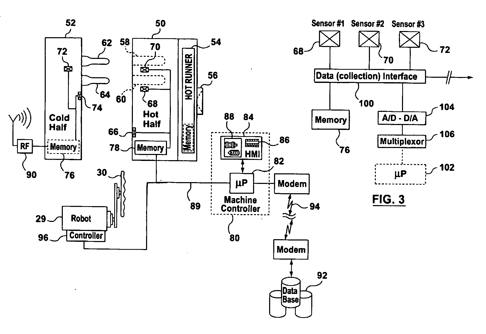
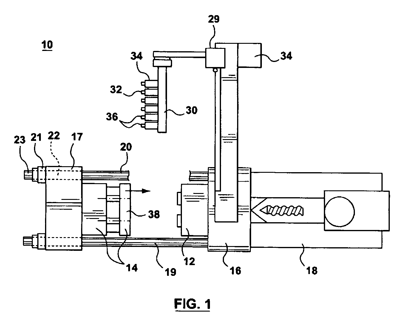
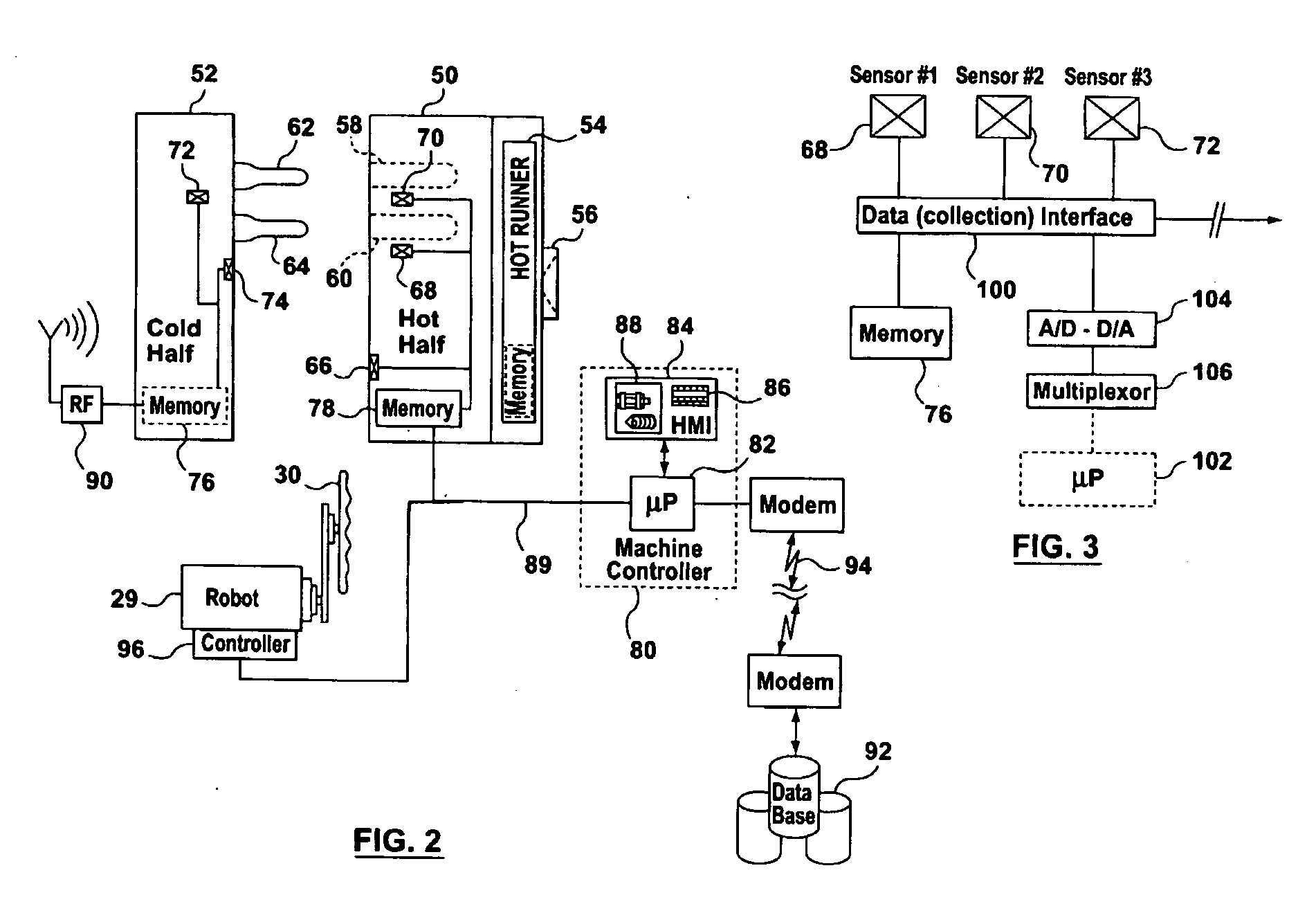
[0029]FIG. 1 shows a typical injection molding machine 10 that can be adaptable to support the control processing intelligence of the present invention. As will be understood, during each injection cycle, the molding machine 10 produces a number of plastic parts corresponding to a mold cavity or cavities defined by complementary mold halves 12, 14 located within the machine 10. Overall operational control of the molding machine is accomplished through use of a machine controller which may be realized by an architecture having distributed intelligence, i.e. multiple interconnected processors that are responsible for the control of individual parts of the molding system. The machine controller is operationally responsible for a human machine interface (shown in FIG. 2) that allows graphical representation of the machine's present or historic status, as well as the entry of information through a touch-screen, keyboard, readable data device (such as a disk drive or CD-ROM) and the like....


PUM

PropertyMeasurementUnit
Fractionaaaaaaaaaa
Fractionaaaaaaaaaa
Fractionaaaaaaaaaa

Abstract

Rather than developing full closure tonnage for a substantial portion of the duration of an injection cycle, closed loop control of the clamp pressure (such as through control of hydraulic pistons) permits clamp pressure to balance exactly, but preferably slightly exceed, the instantaneous injection pressure. A first approach mimics the injection pressure profile with time, whereby applied tonnage is varied with time according to sensed pressure measurements. A second approach looks to pre-stored or historically accumulated injection pressure information and, instead of varying the tonnage, applies a constant tonnage reflecting the maximum recorded or most likely injection pressure to be experienced in the mold (as recorded stored in a look-up table associated with the particular mold configuration). A machine controller (80, 82) causes the application of applied tonnage through the platen (16, 17) and tie-bars (19, 20) of an injection molding machine (10). Pressure sensors (66-74) located either on a mold surface (50), relative to stack components (58-64) and/or relative to a force closure path of permit a microprocessor (82) to control applied clamp closure tonnage. In this way, the system consumes less power and component wear is reduced.

Description

BACKGROUND OF THE INVENTION [0001] 1. Field of the Invention [0002] The present invention relates, in general, to the management of mold operation and the accumulation and use of data to improve all aspects of short-term and long-term mold operation and machine operation / collaboration. More particularly, but not exclusively, the present invention relates to the control of clamp tonnage through closed loop control and the use of sensed or historically stored clamp tonnage information. [0003] 2. Summary of the Prior Art [0004] In a molding operation, whether this be in an injection molding environment or any similar system using platens and molds, molded part quality is affected by a number of factors, including the physical conditions and configuration of the system equipment and also the processing conditions under which the molded part is formed. [0005] With molds required to run essentially on a continuous, year-long basis and under harsh operating conditions (arising from large t...

Claims


Application Information

Patent Timeline
IPC IPC(8): B29C45/76
CPCB22D17/007B22D17/32B29C45/7653B29C2045/1796B29C2945/76006B29C2945/76204B29C2945/76214B29C2945/76234B29C2945/76254B29C2945/76257B29C2945/76381B29C2945/76384B29C2945/76498B29C2945/76505B29C2945/76702B29C2945/76709B29C2945/76785B29C2945/76859B29C2945/76862B29C2945/76933B29C2945/76936B29C2945/76939B29K2067/00B29K2069/00B29C2945/76103B29C45/76B29C45/64
Inventor SAGGESE, STEFANO M.QUAIL, JOHN P.
Owner HUSKY INJECTION MOLDING SYST LTD
Why Eureka
Try Eureka