Piezoelectric resonator element and piezoelectric device

a piezoelectric device and resonator element technology, applied in the direction of device material selection, turn-sensitive devices, instruments, etc., can solve the problems of high instability and difficult control, and achieve compact size of the entire structure, improve temperature characteristics, and good miniaturization temperature characteristics

Active Publication Date: 2006-04-20
SEIKO EPSON CORP
View PDF12 Cites 40 Cited by
  • Summary
  • Abstract
  • Description
  • Claims
  • Application Information

AI Technical Summary

Benefits of technology

[0017] An advantage of the invention is to provide a piezoelectric resonator element and a piezoelectric oscillator that have a good temperature characteristic for miniaturization.
[0018] The above advantage is achieved in a first aspect of the invention with a piezoelectric resonator element that is provided with a base that is formed of a piezoelectric material and has a given length, and a plurality of vibration arms which extend from one part of the base, and further, a supporting arm that extends from another part of the base spaced apart from the one part by the given length in a width direction, and the supporting arm extending in the same direction as the vibration arms outboard the vibration arms.
[0019] According to the structure of the first aspect of the invention, the vibration arms that perform flexural vibration extend from one part of the base, while the supporting arm extends from another part of the base having the given length.
[0020] Because of the structure, after the supporting arm is bonded to a base substrate such as a package by adhesive bonding or the like, a stress change, which is produced at the bonding position due to the change of surrounding temperature or drop shock or the like, hardly affects the vibration arms from the bonding position of the supporting arm through the other part of the base, and further, through the distance of the given length of the base. As a result, particularly, the temperature characteristic is improved.
[0021] Also, in contrast, vibration leakage from the vibration arms that perform flexural vibration is hardly propagated to the supporting arm, since the vibration leakage reaches the supporting arm spaced apart from the base by the given length of the base. Namely, if the length of the base is extremely short, a situation that is difficult to control may occur since a leaked component of the flexural vibration spreads over the supporting arm. However, in the invention, such a situation is thoroughly avoided.
[0022] In addition to the advantageous effects, since the supporting arm extends from the other part of the base in the width direction, and extends in the same direction as the vibration arm outboard the vibration arms, the size of the entire structure can be made compact.

Problems solved by technology

However, the piezoelectric resonator element 1, which is miniaturized, has the following problem in its temperature characteristics.
However, the temperature-CI value characteristic shown in FIG. 19 has a problem in that it is highly unstable.
Namely, if the length of the base is extremely short, a situation that is difficult to control may occur since a leaked component of the flexural vibration spreads over the supporting arm.

Method used


Image

  • Piezoelectric resonator element and piezoelectric device
  • Piezoelectric resonator element and piezoelectric device
  • Piezoelectric resonator element and piezoelectric device

Examples


second embodiment and third embodiment

[0086]FIGS. 5 and 6 respectively show the piezoelectric resonator element according to a second embodiment and a third embodiment of the invention. They show examples in which a low stiffness structure is employed to a part of the supporting arm. The parts shown in these drawings that are common to the piezoelectric resonator element 32 described in FIGS. 1 and 2 are given the same reference numerals, and a duplicate description thereof will be omitted here. Below, differences will be mainly described.

[0087] In these embodiments, the low stiffness structure is disposed at a position between the base 51 and the conductive adhesive 43, which is applied at the bonding position. As a result, even if the vibration leakage from the flexural vibration of the vibration arms reaches the supporting arms, the likelihood of it reaching the bonding position can be reduced as much as possible.

[0088] In the piezoelectric resonator element 32-1 in FIG. 5, the low stiffness structure is a reduced ...

fourth embodiment

[0093]FIGS. 7 and 8 show the piezoelectric device according to a fourth embodiment of the invention. FIG. 7 is a schematic plan view thereof, and FIG. 8 is a schematic sectional-view taken along the B-B line in FIG. 7. In addition, FIG. 9 is an enlarged plan view to explain the details of the piezoelectric resonator element 32 in FIG. 7. FIG. 10 is a schematic sectional-view taken along the C-C line on vibration arms in FIG. 7.

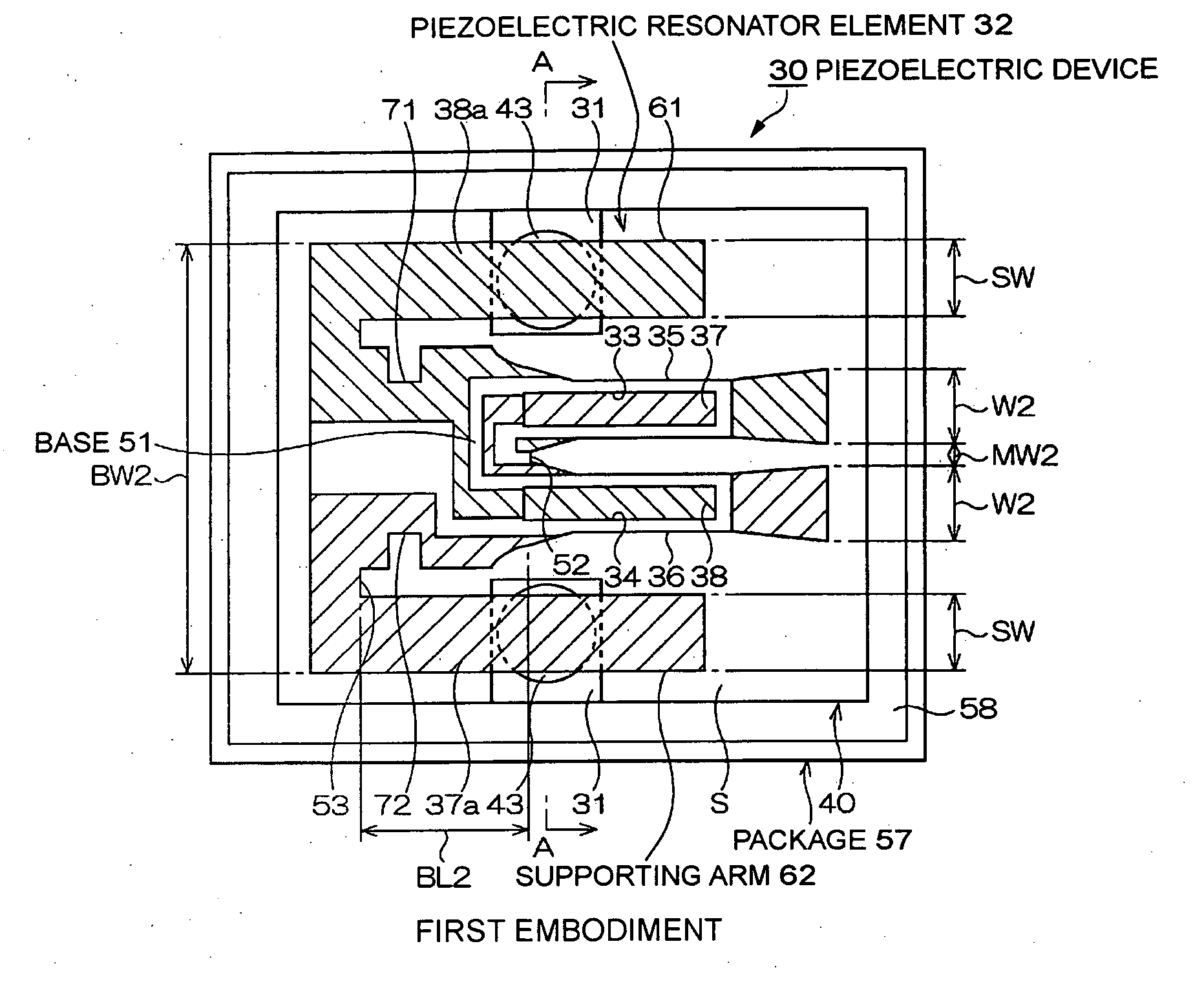
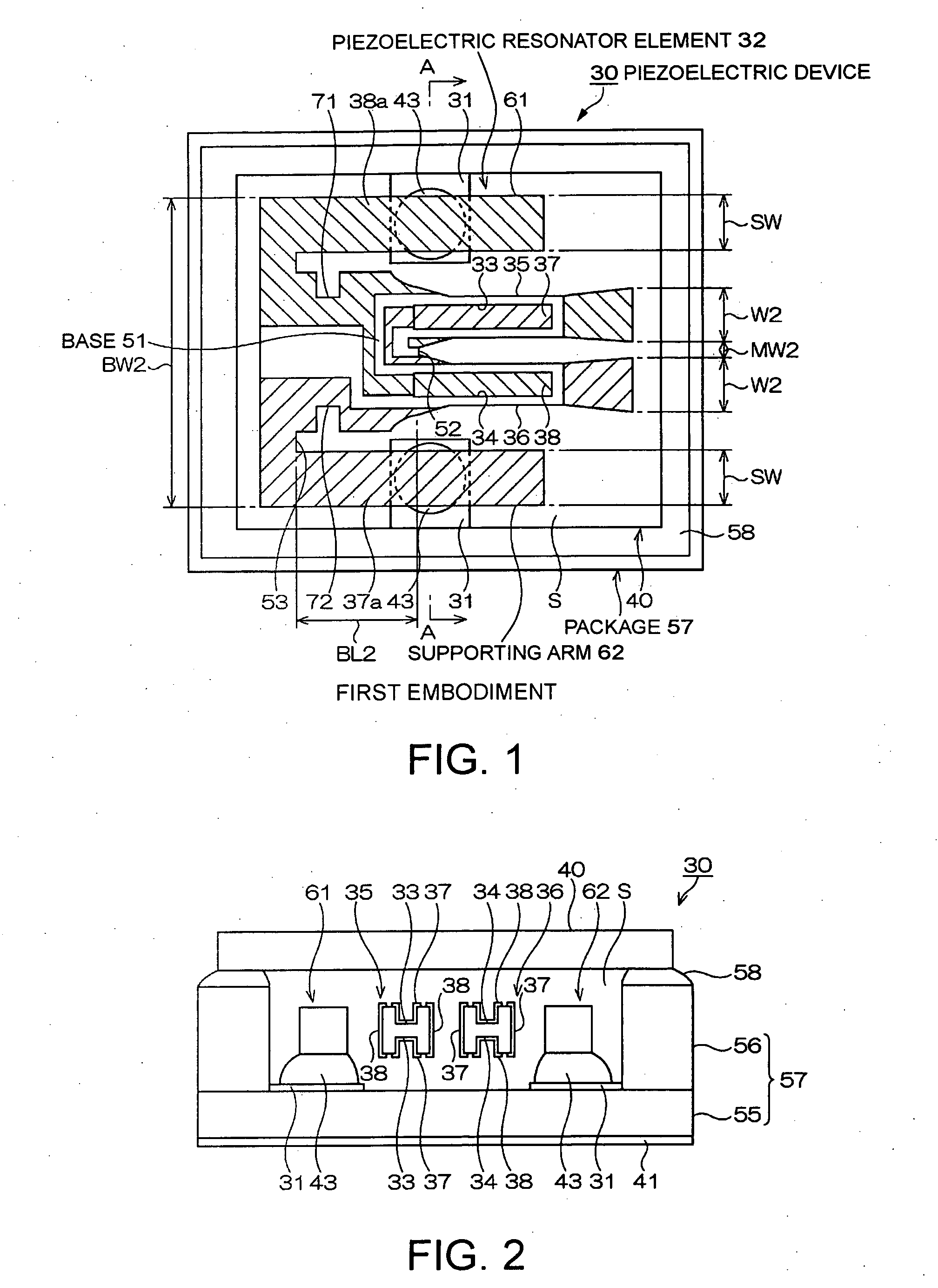
[0094] In the structure of the piezoelectric device 30-1 shown in FIGS. 9 and 10, since the parts given the same numerals of those of the piezoelectric device 30 described in FIG. 1 are common structures, a duplicate description thereof will be omitted here. Below, differences will be mainly described.

[0095] The package 57-1, which is formed, for example, in a rectangular box shape as shown in FIGS. 7 and 8, differs from the package 57 in FIG. 1 in that it is formed by laminating the following three substrates: a substrate 54 as a first substrate, the substr...

fifth embodiment to seventh embodiment

[0139]FIG. 13 is a schematic plan view illustrating the piezoelectric resonator element according to a fifth embodiment of the invention.

[0140] As for a piezoelectric resonator element 32-4 of the fifth embodiment, the structure that is common to that of the piezoelectric resonator element 32-3 of the fourth embodiment is given the same numerals. A duplicate explanation of thereof is omitted. Differences will be explained below.

[0141] Each of the piezoelectric resonator elements 61 and 62 in FIG. 13 includes bonding positions, which serve as the coating region of the conductive adhesive, indicated as the numeral 43, and cut parts 75-1 and 76, which serve as a structure lowering the stiffness and are on the way to the base 51. The cut parts 75-1 and 76 are the same as those of the third embodiment in FIG. 6 in the viewpoint that they are formed at the outer side edge and the inner side edge in the vicinity of the base end part of each of the supporting arms. Similar to the third em...


PUM


Abstract

A piezoelectric resonator element including: a base formed of a piezoelectric material and having a given length; a plurality of vibration arms extending from one part of the base; and a supporting arm extending from another part of the base spaced apart from the one part of the base by the given length in a width direction, the supporting arm extending in a common direction with the vibration arms outboard the vibration arms.

Description

RELATED APPLICATIONS [0001] This application claims priority to Japanese Patent Application No. 2004-305621 filed Oct. 20, 2004 and 2005-129906 filed Apr. 27, 2005 which are hereby expressly incorporated by reference in their entirety. BACKGROUND [0002] 1. Technical Field [0003] The present invention relates to an improvement on a piezoelectric resonator element and a piezoelectric device including the piezoelectric resonator in its package or case. [0004] 2. Related Art [0005] Piezoelectric devices, including a piezoelectric resonator, a piezoelectric oscillator and the like, have been widely used for small information equipment, such as hard disc drives (HDDs), mobile computers, and integrated circuit (IC) cards, and for mobile communications equipment such as mobile phones, car-phones, and paging systems, and piezoelectric gyro sensors, etc. [0006]FIG. 17 is a schematic plan view illustrating an example of a piezoelectric resonator element conventionally used in the piezoelectric...

Claims


Application Information

Patent Timeline
Patent Type & Authority Applications(United States)
IPC IPC(8): H03H9/21G01C19/56H01L41/09H01L41/18H01L41/22H01L41/23H01L41/332H03H9/09H03H9/10
CPCG01C19/5607H03H9/02086H03H9/02102H03H9/0519H03H9/0595H03H9/1021H03H9/21H03H2003/026H03H2003/0492H03B5/32H03H9/19
Inventor TANAYA, HIDEO
Owner SEIKO EPSON CORP
Why Eureka
Try Eureka