

Donor substrate and fabrication method of organic light emitting display using the same
a technology of donor substrate and fabrication method, which is applied in the direction of diffusion transfer process, thermography, instruments, etc., can solve the problems of high price of laser apparatus with high accuracy and increase the fabrication cost of organic light emitting display, and achieve the effect of accurate formation of minute transfer layer pattern
- Summary
- Abstract
- Description
- Claims
- Application Information
AI Technical Summary
Benefits of technology
Problems solved by technology
Method used
Image

Examples
first embodiment
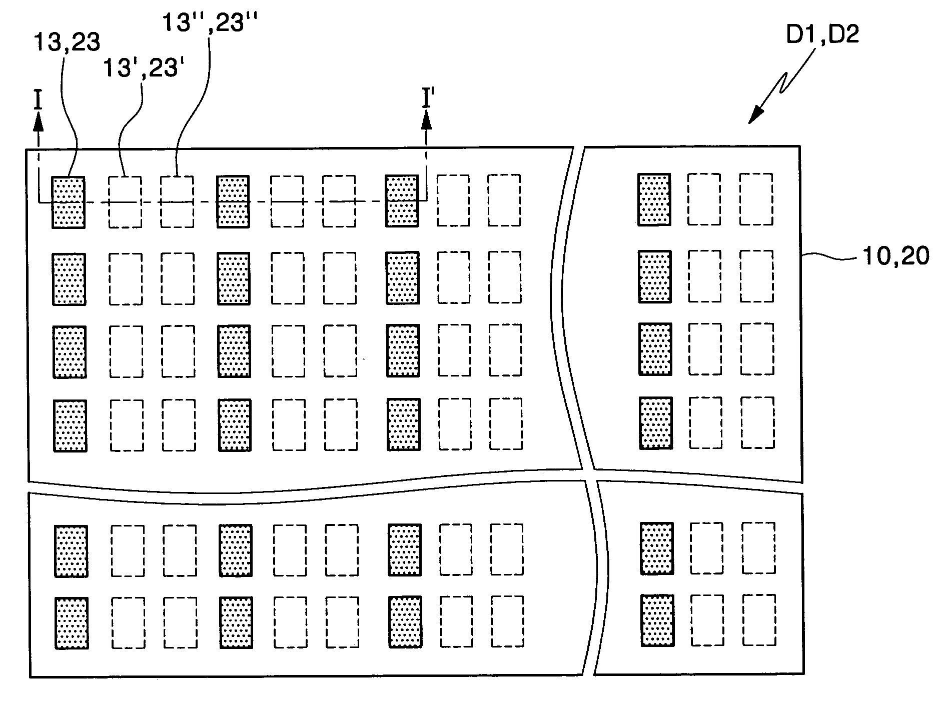
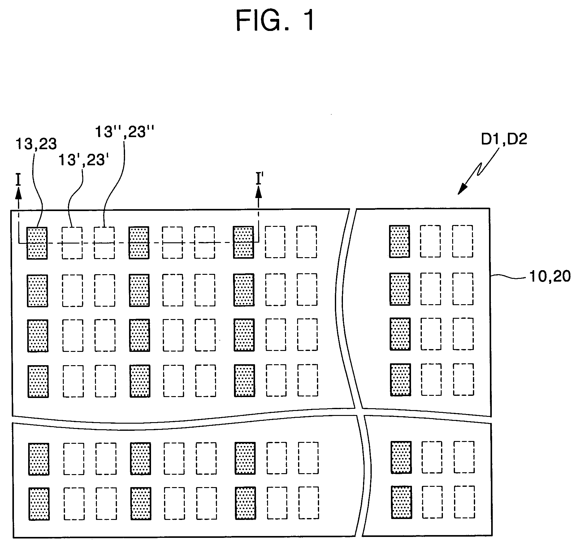
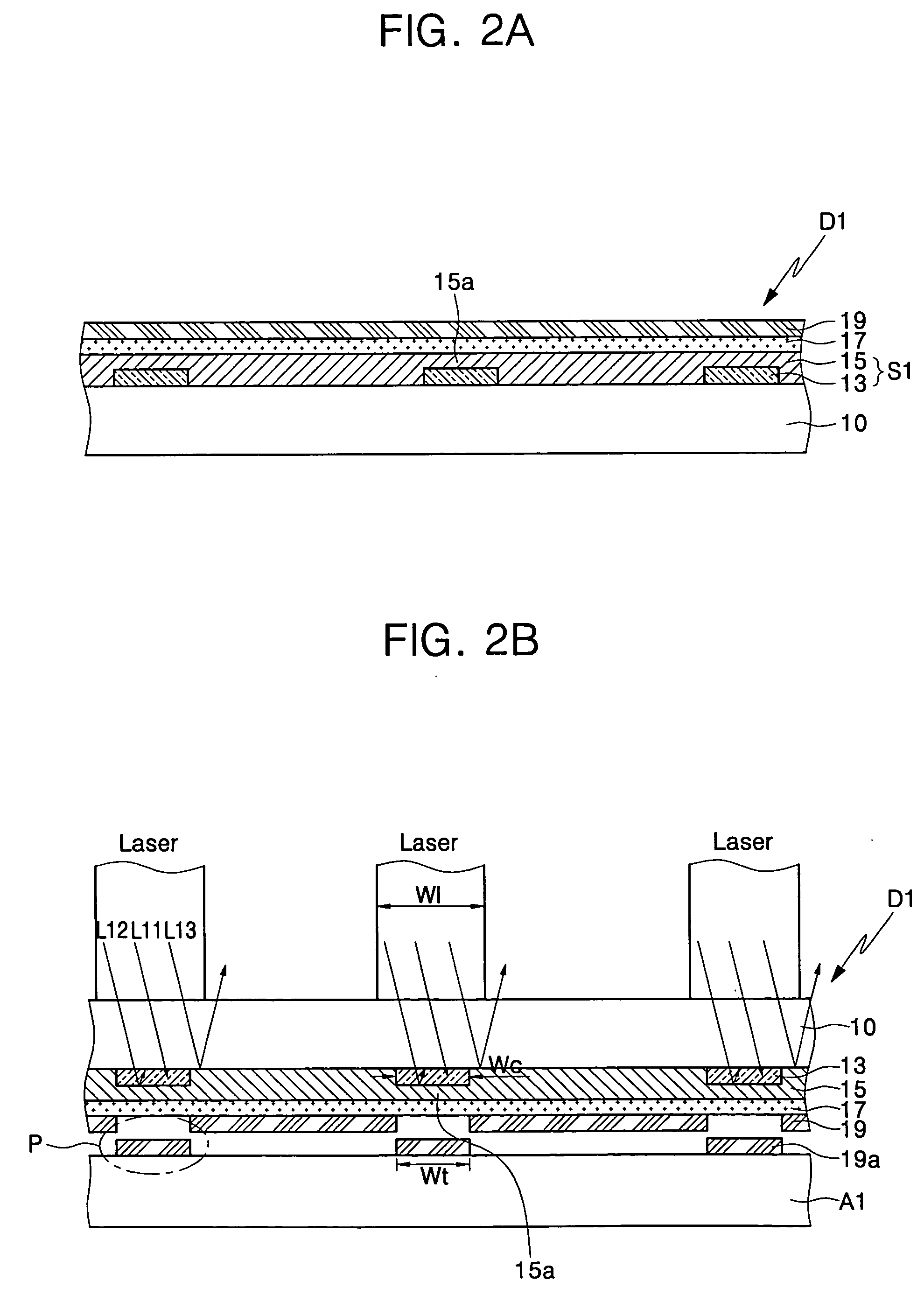
[0027]FIG. 2A is a cross-sectional view taken along Line I-I′ of FIG. 1, and shows a donor substrate according to the present invention.
[0028] Referring to FIG. 2A, the donor substrate D1 comprises a base substrate 10. Preferably, the base substrate 10 has a high permeability for a laser beam, high thermal resistance, and proper flexibility and mechanical strength. Therefore, the base substrate 10 may be made of a polyester film. Specifically, the base substrate 10 may be made of a polyethylene terephthalate film or a polyethylene naphthalate film. The thickness of the base substrate 10 preferably ranges from 10 mm to 500 μm.
[0029] A transfer layer 19 is disposed on the base substrate 10. The transfer layer 19 is disposed on the entire top surface of the base substrate 10. The transfer layer 19 may be an electroluminescent organic layer, in other words, an emission layer. Moreover, the transfer layer 19 may further comprise at least one layer selected from a group consisting of a h...
second embodiment
[0042]FIG. 3A is a cross-sectional view taken along Line I-I′ of FIG. 1, and shows a donor substrate according to the present invention. The donor substrate according to the present embodiment is similar to the donor substrate described with reference to FIG. 2A, except as described below.
[0043] Referring to FIG. 3A, a donor substrate D2 comprises a base substrate 20 and a transfer layer 29 disposed on the base substrate 20.
[0044] A selective heat generation structure S2 is interposed between the base substrate 20 and the transfer layer 29. The selective heat generation structure S2 comprises a heat generation region from which heat is generated by light-to-heat conversion, and a heat non-generation region adjacent to the heat generation region.
[0045] The selective heat generation structure S2 comprises light-to-heat conversion (LTHC) layer patterns 23 selectively disposed on parts of the base substrate 20. In the present embodiment, the base substrate 20 has recessed regions 20a,...
third embodiment
[0056]FIG. 5A is a cross-sectional view taken along Line I-I′ of FIG. 4, and shows a donor substrate according to the present invention. The donor substrate according to the present embodiment is similar to the donor substrate described with reference to FIG. 2A, except as described below.
[0057] Referring to FIG. 5A, the donor substrate D3 comprises a base substrate 30 and a transfer layer 39 disposed on the base substrate 30.
[0058] A selective heat generation structure S3 is interposed between the base substrate 30 and the transfer layer 39. The selective heat generation structure S3 comprises a heat generation region from which heat is generated by light-to-heat conversion, and a heat non-generation region contacting the heat generation region.
[0059] The selective heat generation structure S3 comprises reflective layer patterns 31 selectively disposed on parts of the base substrate 30, and light-to-heat conversion layer pattern 33 covering the reflective layer patterns 31. The l...
PUM
| Property | Measurement | Unit |
|---|---|---|
| Transport properties | aaaaa | aaaaa |
| Heat | aaaaa | aaaaa |
| Reflection | aaaaa | aaaaa |
Abstract
Description
Claims
Application Information