
System and method for duplex operation using a hybrid element

a hybrid element and duplex operation technology, applied in the field of radio frequency transmission and reception systems, can solve the problems of low cost, power consumption, switching control,

Inactive Publication Date: 2006-04-27
TIME DOMAIN
View PDF10 Cites 49 Cited by
  • Summary
  • Abstract
  • Description
  • Claims
  • Application Information

AI Technical Summary

Problems solved by technology

One of the problems in small ultra wideband systems is designing a low cost fast duplexer based on a Transmit / Receive (T / R) switch that allows sensing of very close radar signal returns within, for example, a few meters.
Typical T / R switches present power consumption, switching control, and settling time issues which limit their switching speed to a few nanoseconds.
T / R switches can be used, but can be disadvantageous in terms of element costs and the need for specific power voltage levels; particularly when higher power RF is employed.
Separate transmit and receive antennas have also been proposed, but the use of separate antennas increases the antenna footprint and can present difficult configuration issues.
Band splitting diplexers can defeat the wide bandwidth of UWB and are not appropriate for systems that must use the same frequency band for both transmit and receive.

Method used


Image

  • System and method for duplex operation using a hybrid element
  • System and method for duplex operation using a hybrid element
  • System and method for duplex operation using a hybrid element

Examples


Embodiment Construction

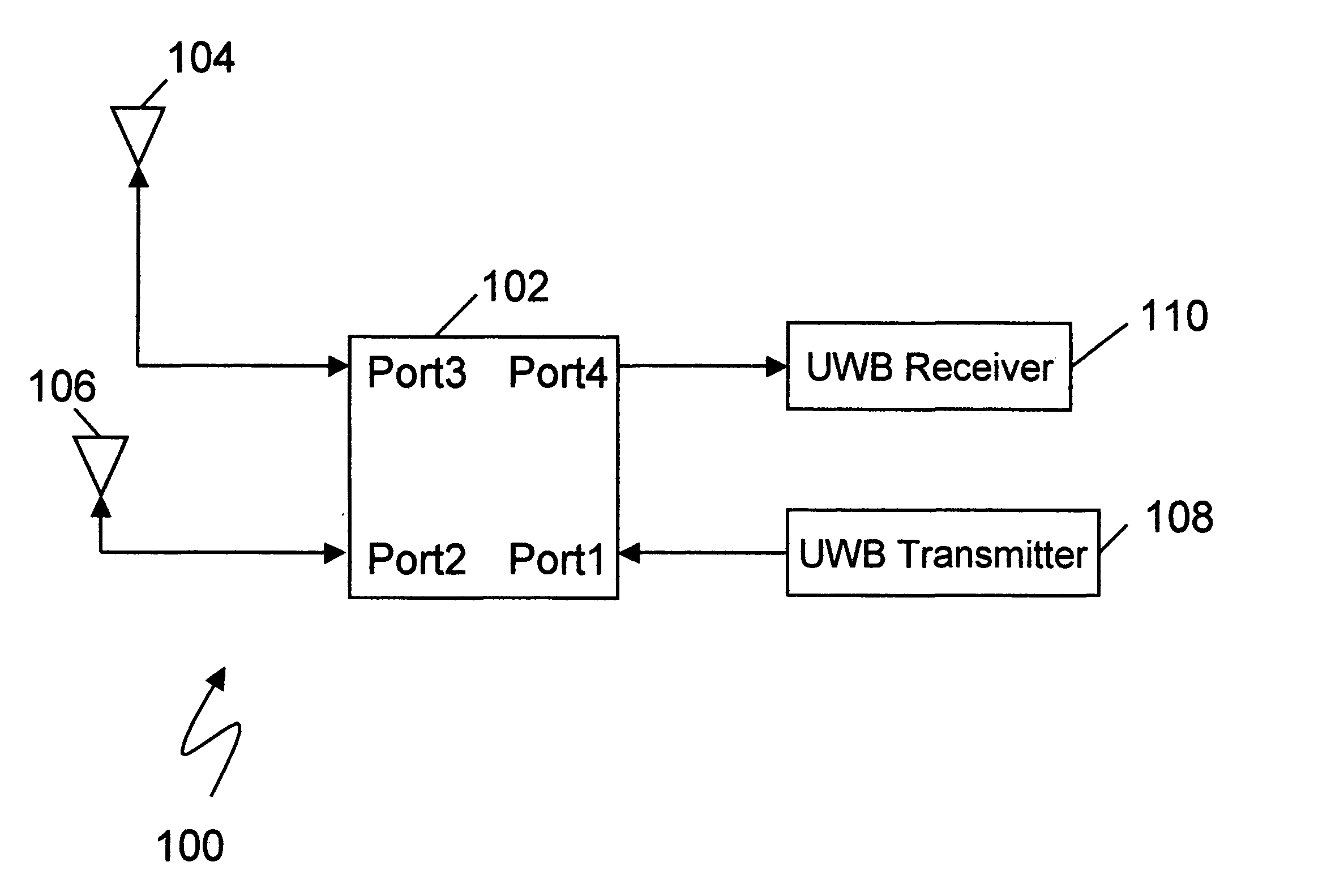
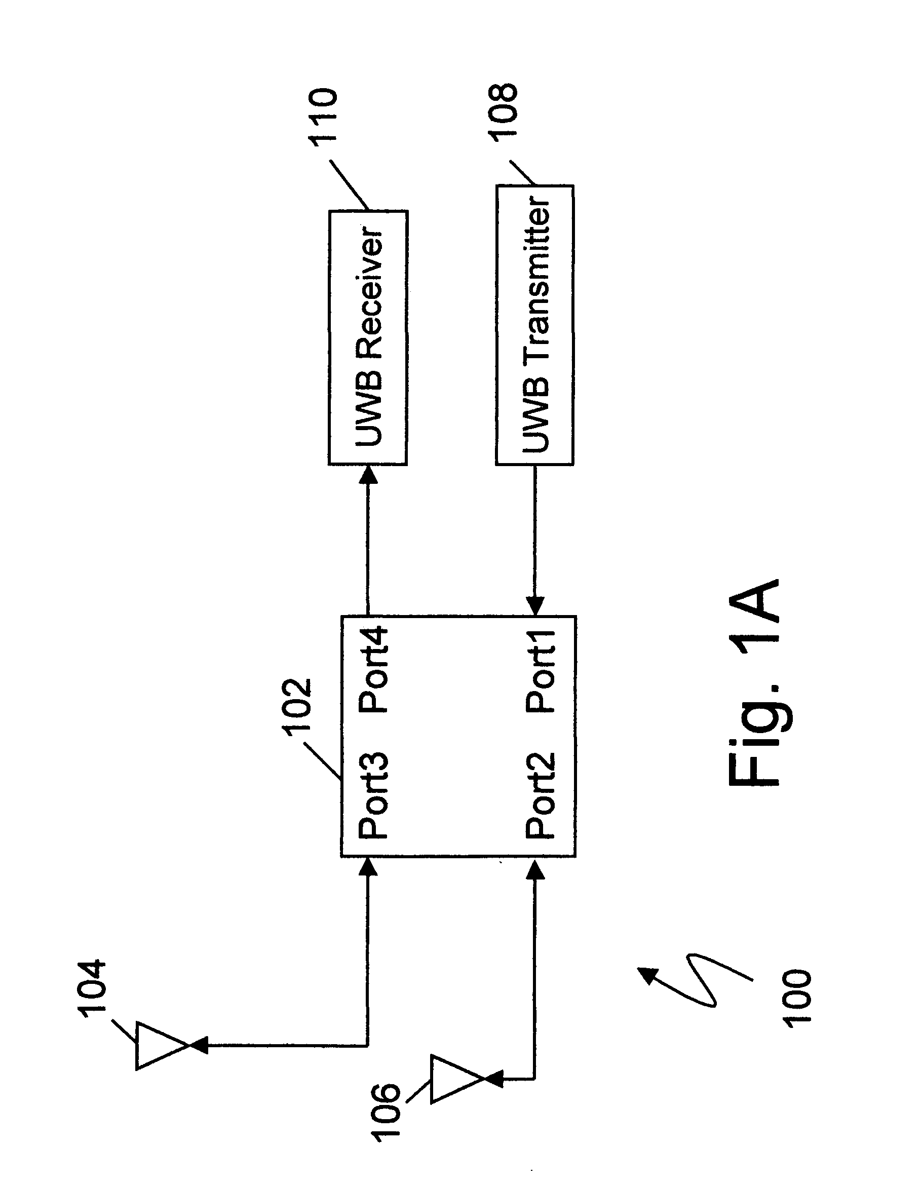
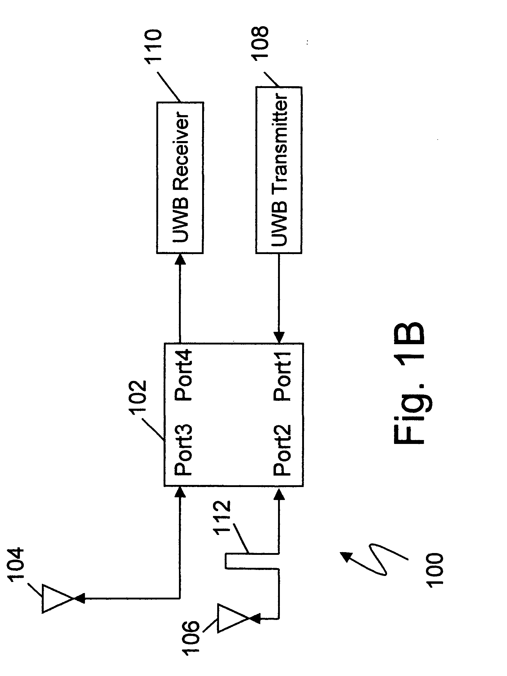
[0018] The present invention utilizes a hybrid coupler to couple two cross polarized antennas to a transmitter and receiver. The transmitter is coupled to the hybrid input port and the receiver is coupled to the hybrid isolated port.

[0019] Since the hybrid coupler is a low loss, passive device, it consumes no DC power and contributes very little RF loss. Further, hybrid couplers can handle very high RF power levels and may be made using low cost strip line techniques making them suitable for consumer and commercial applications.

[0020] Since the hybrid includes no switching operations, switching time and settling time considerations of a T / R switch are nonexistent, enabling very close timing of transmit and receive, even to include overlapping operation, which enables close range radar and sensing devices.

Ultra Wideband Background

[0021] The following is an overview of impulse radio as an aid in understanding the benefits of the present invention.

[0022] Ultra Wideband is an emer...


PUM


Abstract

A system for duplex transmission and reception utilizing circular polarization wherein a pair of linear polarized orthogonal antennas is coupled to a transmitter through a hybrid coupler and a receiver is coupled to the antennas via the same hybrid coupler by using the port isolated from the transmitter. The hybrid may be a quadrature hybrid coupler or may comprise a 180 degree hybrid combined with a 90 degree phase shift network. Embodiments are shown for receiving a first reflection (opposite handed sense) circular polarized wave and alternatively, for receiving a second reflection (same handed sense) (multi-path) circular polarized wave.

Description

FIELD OF THE INVENTION [0001] The present invention pertains generally to the field of radio frequency transmission and reception systems, and more particularly to duplex operation of transmitters and receivers utilizing circular polarized signals. BACKGROUND OF THE INVENTION [0002] Modern RF devices are following the path of computer devices by becoming smaller, lower cost and are proliferating in application, increasingly used in consumer and commercial applications. As more applications are pursued, there is pressure to lower the cost, size and complexity of the RF components to meet marketing requirements for the new devices. [0003] Ultra Wideband radar is increasingly proposed to solve problems such as security systems, detection and measurement of objects, assessment of materials, detection of objects in the ground, and many more. [0004] One of the problems in small ultra wideband systems is designing a low cost fast duplexer based on a Transmit / Receive (T / R) switch that allow...

Claims


Application Information

Patent Timeline
Patent Type & Authority Applications(United States)
IPC IPC(8): H01P5/18
CPCG01S7/026G01S7/03G01S13/0209H01Q21/26
Inventor FITZPATRICK, DOUGLAS D.FLUHLER, HERBERT U.TROUTMAN, DENNIS L.RICHARDS, JAMES L.
Owner TIME DOMAIN
Learn More