Surface-mount capacitor and method of producing the same

Active Publication Date: 2006-04-27
TOKIN CORP
View PDF4 Cites 28 Cited by
  • Summary
  • Abstract
  • Description
  • Claims
  • Application Information

AI Technical Summary

Benefits of technology

[0035] Preferably, the strip-like plate is made of copper or copper alloy subjected to plating, the strip-like plate being welded by laser welding after the etching layer of the anode lead portion is removed. By removing the etching layer also in case of the laser welding, the bonding strength upon welding is increased and the yield is improved.
[0036] Preferably, in the step of forming the multilayer capacitor structure by laminating the capacitor elements after a connecting strip-like plate is welded to the anode lead portion of each of the capacitor elements, laser welding is carried out by setting an irradiating position such that a part of a laser beam section spreads beyond an end of each of the anode lead portion and the strip-like plate and irradiating the laser beam so that the laser beam penetrates or passes through the anode lead portions and the strip-like plates of all the capacitor elements and that a welded portion is exposed on an end face of the multilayer capacitor structure. By the laser welding, the anode lead portions of the multilayer capacitor structure are simultaneously bonded. In addition, if the laser were cast at an inner position, for example, at the center of the anode lead portion, then a through hole of a closed circle would penetrate the anode lead portion and melting occurs in the through hole. In this case, part of melted material may often adhere to an internal surface of the through hole to be confined or accumulated in the through hole. On the other hand, according to this technique, since the welded portion is exposed on an end face of the multilayer capacitor structure, an excellent welding mark (penetration) is formed without confinement or accumulation of the melted material i

Problems solved by technology

In a production process of the surface-mount capacitor, there are various problems.
For example, in ultrasonic welding of the anode lead portion, deformation due to thermal expansion is large so that the improvement in dimensional accuracy is not easy.
Further, it is not easy to prevent pro

Method used


Image

  • Surface-mount capacitor and method of producing the same
  • Surface-mount capacitor and method of producing the same
  • Surface-mount capacitor and method of producing the same

Examples


Example

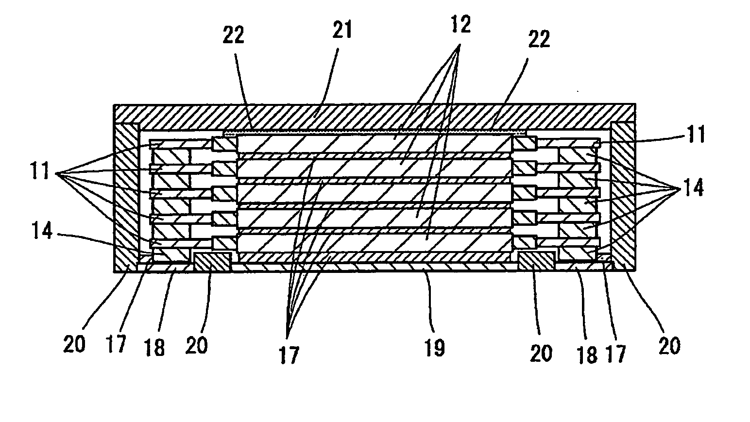
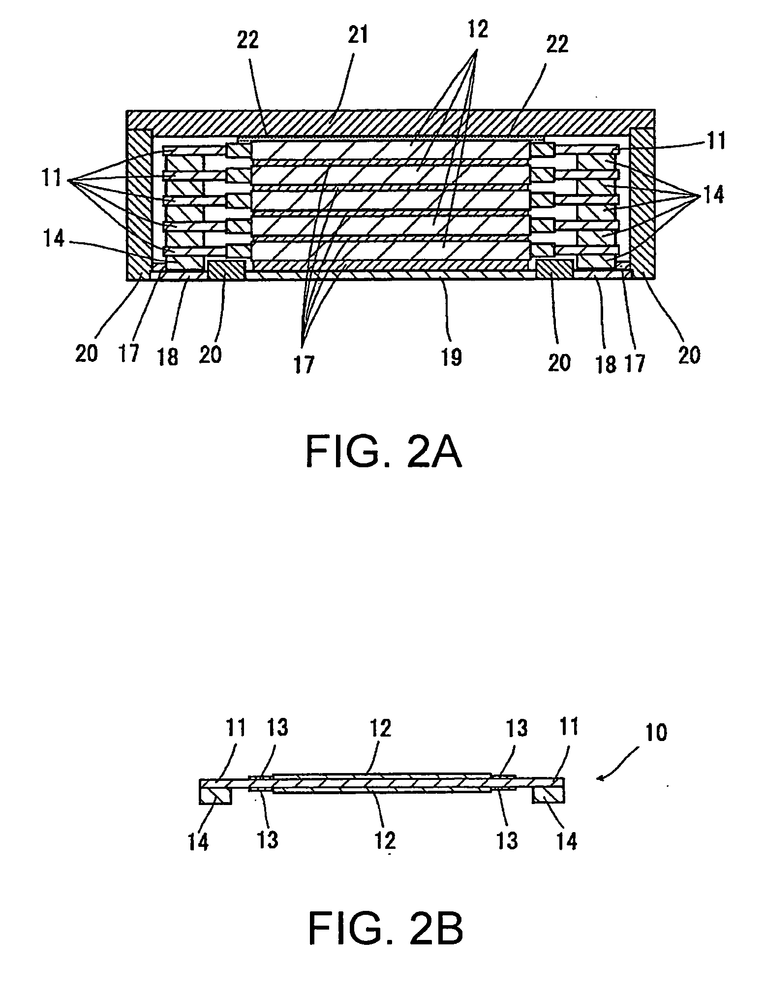
[0075] Referring to FIGS. 2A and 2B, a surface-mount capacitor according to a first embodiment of this invention includes a plurality of (five in the illustrated example) capacitor elements 10 each having a rectangular plate-like shape and laminated into a multilayer capacitor structure.

[0076] Referring to FIGS. 3A and 3B together with FIGS. 2A and 2B, the surface-mount capacitor has anode terminals 18 connected to anode lead portions 11 of the capacitor elements 10, a cathode terminal 19 connected to cathode portions 12 of the capacitor elements 10, a mold resin case 20 accommodating the capacitor elements 10, and a cap 21 covering the mold resin case 20.

[0077] Turning back to FIGS. 2A and 2B, each capacitor element 10 has the anode lead portions 11 formed at opposite ends thereof, the cathode portion 12 formed at the center, and insulating resin layers 13 separating or isolating the anode lead portions 11 and the cathode portion 12 from each other. In FIG. 2A, a section of each ...

Example

[0089] Referring to FIG. 12, a surface-mount capacitor according to a second embodiment of this invention is similar to that of the first embodiment except that the cap 21 (FIG. 2A) is replaced by an exterior case 23 of a box-like shape. Similar parts are designated by like reference numerals and description thereof will be omitted.

[0090] The exterior case 23 illustrated in FIG. 13A is fitted over the mold resin case 20 illustrated in FIG. 13B to complete a case assembly. Referring to FIGS. 14A and 14B, the exterior case 23 has a lower end higher than the upper surfaces of the anode and the cathode terminals 18 and 19. With this structure, it is possible to prevent the lower end of the exterior case 23 from contacting the anode or the cathode terminals 18 or 19 due to thermal expansion during reflow soldering to bend the anode or the cathode terminals 18 or 19 so that a main body of the surface-mount capacitor is lifted up. Like in the first embodiment, the end portion of each of t...

Example

[0097] Either in case of the single-layer structure as in the third embodiment or in case of the multilayer structure as in the first and the second embodiments, a common process can be used except the step of producing the multilayer capacitor structure and the difference in height of the mold resin case and the exterior case. Thus, it is possible to obtain a capacitor series of surface-mount capacitors excellent in productivity.

[0098] While this invention has thus far been disclosed in conjunction with the preferred embodiments thereof, it will be readily possible for those skilled in the art to put this invention into practice in various other manners within the scope of the appended claims.


PUM

PropertyMeasurementUnit
Thicknessaaaaaaaaaa
Shapeaaaaaaaaaa
Electrical conductoraaaaaaaaaa

Abstract

A surface-mount capacitor includes a multilayer capacitor structure formed by laminating plate-like capacitor elements each having anode lead portions 11 at opposite ends thereof and a cathode portion 12 at the center, an anode terminal 18 connected to each anode lead portion 11 via a strip-like plate 14, and a cathode terminal 19 connected to the cathode portion 12. The anode and the cathode terminals 18 and 19 have a flat shape and are formed on a common plane as a substrate-mounted surface. A mold resin case 20 has a bottom portion filling a gap between the anode and the cathode terminals 18 and 19 and mechanically connecting the anode and the cathode terminals 18 and 19, and side walls substantially perpendicular to the substrate-mounted surface. The anode and the cathode terminals 18 and 19 have upper surfaces exposed on an inner bottom surface of the mold resin case 20 to be connected to the anode lead portions 11 and the cathode portion 12.

Description

[0001] This application claims priority to prior Japanese patent application JP 2004-311928, the disclosure of which is incorporated herein by reference. BACKGROUND OF THE INVENTION [0002] This invention relates to a surface-mount capacitor for a power supply line and, in particular, to a surface-mount capacitor suitable for use in a decoupling circuit for a stabilized power supply connected to a CPU and a method of producing the same. [0003] Development has been made of a surface-mount capacitor which is called a transmission-line element or a transmission-line noise filter and which has characteristics of both a capacitor and a filter, with a capacitance of several hundreds of microfarads, an ESR (equivalent series resistance) of 5 mΩ in a frequency band of 100 MHz, and an ESL (equivalent series inductance) of about 1 pH. The above-mentioned surface-mount capacitor comprising a unit capacitor element is particularly suitable for use in a decoupling circuit of a power supply line c...

Claims


Application Information

Patent Timeline
IPC IPC(8): H01G4/228
CPCH01G9/008Y10T29/417H01G9/08H01G4/224H01G4/228H01G4/30H01G4/33
Inventor NAGASAWA, TOSHIHISAARAKI, KENJITAKATA, HITOSHIKAWAI, AKIHIROARAI, SHINJI
Owner TOKIN CORP
Why Eureka
Try Eureka