Q-modulated semiconductor laser

a semiconductor laser and modulator technology, applied in semiconductor lasers, laser optical resonator construction, laser details, etc., can solve the problems of limiting the transmission distance, the fundamental speed limit of direct modulated lasers, and the chirp of wavelengths in direct modulated lasers

Inactive Publication Date: 2006-04-27
LIGHTIP TECH
View PDF13 Cites 40 Cited by
  • Summary
  • Abstract
  • Description
  • Claims
  • Application Information

AI Technical Summary

Benefits of technology

[0016] a second optical waveguide connected to the first optical waveguide, said second optical waveguide being sandwiched between a second pair of electrodes for providing an electrical means to adjust the effective refractive index of said second optical waveguide,

Problems solved by technology

However, the directly modulated laser has fundamental speed limits, and will display transient oscillation at a frequency equal to its relaxation oscillation frequency.
Wavelength chirp is another problem arising in directly modulated lasers.
Due to chromatic dispersion in optical fibers, pulse spreading is more severe in the case of a wider laser linewidth, thereby limiting the transmission distance.
However, the phase change associated with the direct modulation often interferes with the wavelength tuning mechanism and the stability of the laser.
Although the EAM improves the chirp performance considerably compared to direct modulation of the laser, the chirp problem remains due to refractive index change intrinsically associated with the modulation of absorption coefficient.
However, such an external modulator is very expensive.

Method used


Image

  • Q-modulated semiconductor laser
  • Q-modulated semiconductor laser
  • Q-modulated semiconductor laser

Examples


Embodiment Construction

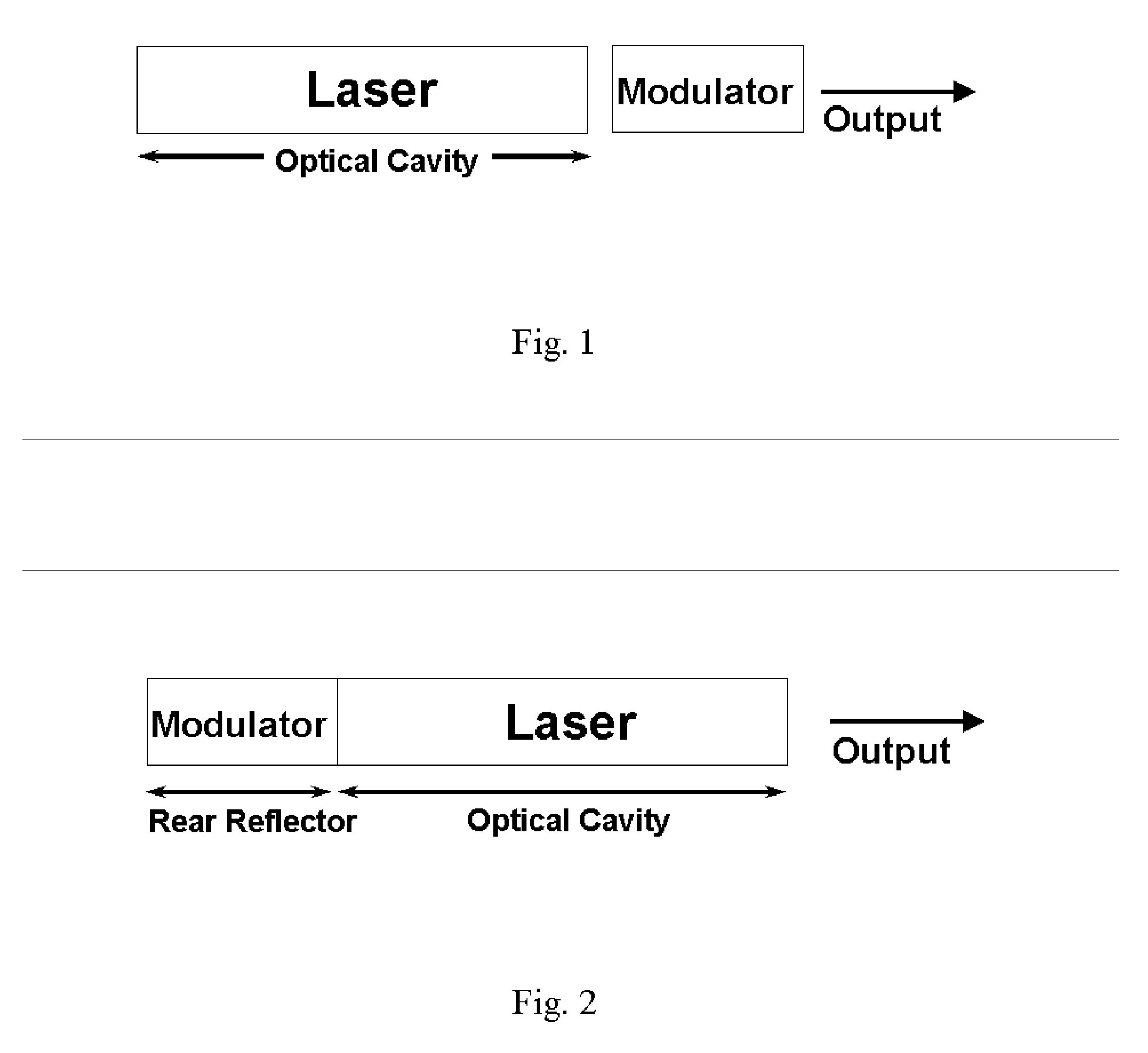
[0038]FIG. 1 is a schematic diagram of a prior-art semiconductor laser modulated by an external modulator or an integrated electro-absorption modulator. The modulator is placed in front of the laser. In the case of an electro-absorption modulator, an electrical signal is applied on the modulator to change its absorption coefficient. The output beam of the laser traverses through the modulator with a low loss when the modulator is in the on-state and is mostly absorbed when the modulator is in the off-state. In the case of a modulator based on Mach-Zehnder interferometer, the modulator is turned on and off by changing the refractive index and consequently the phase in one arm of the interferometer. An example of such devices is described in U.S. Pat. No. 4,558,449 by E. I. Gordon, issued on Dec. 10, 1985.

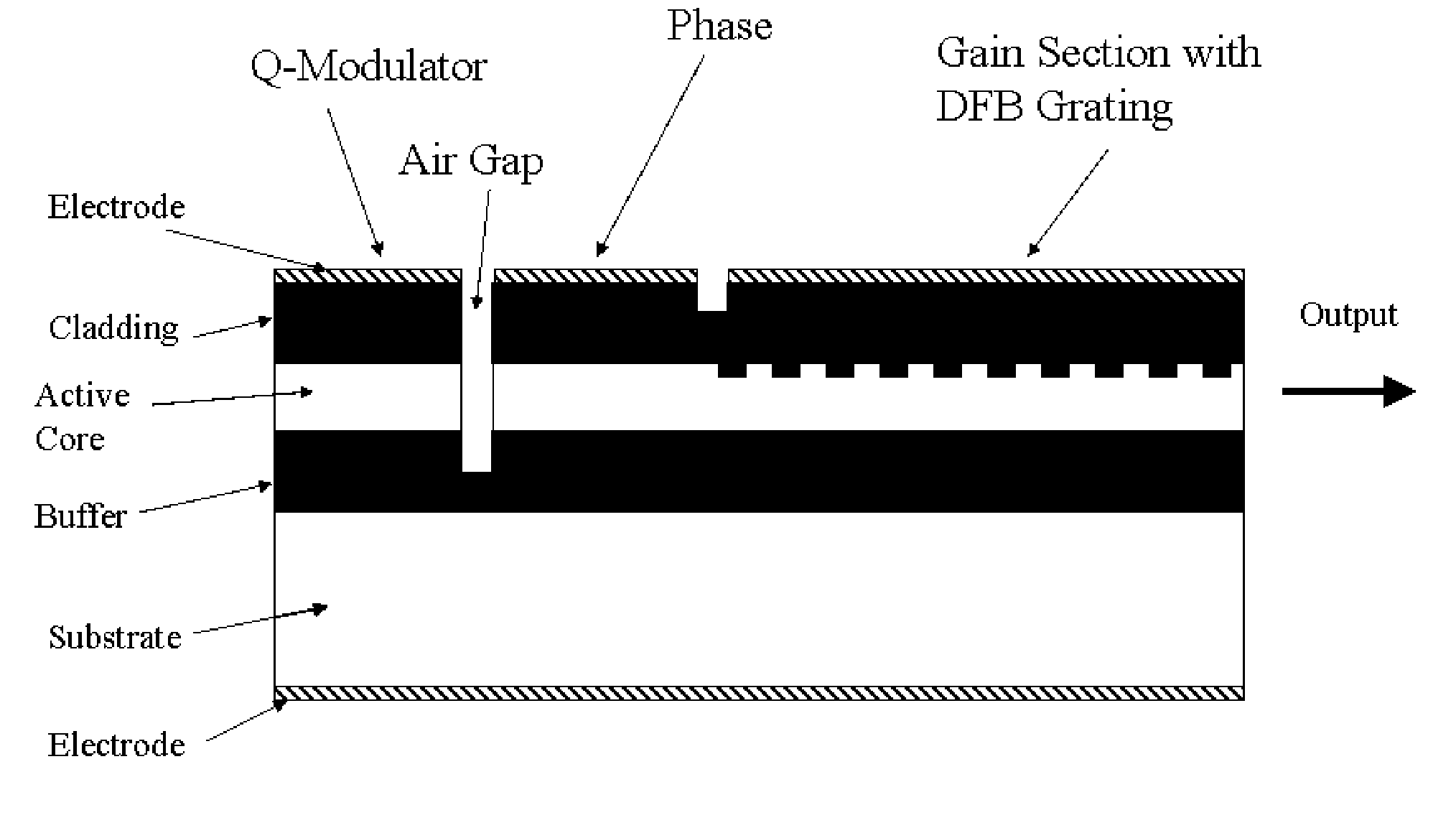
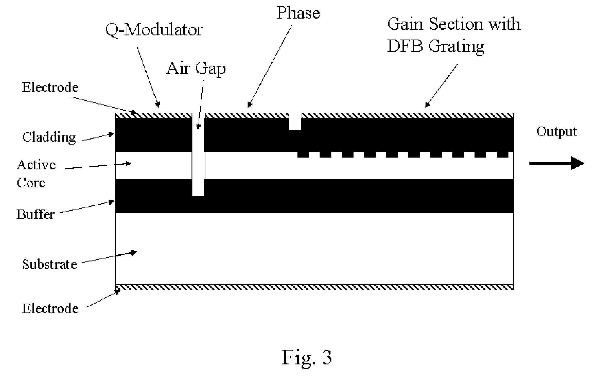
[0039]FIG. 2 is a generic schematic diagram of the semiconductor laser monolithically integrated with a Q-modulator in accordance with the present invention. The modulator is locate...


PUM


Abstract

A Q-modulated semiconductor laser comprises an optical gain section and an electro-absorptive modulator section, separated by a vertically etched air gap acting as a partially reflecting mirror. The modulator section is placed inside an anti-resonant Fabry-Perot cavity and acts as the rear reflector of the laser. The change of the absorption coefficient in the modulator section results in a change in the Q-factor of the laser, and consequently the lasing threshold and output power. Different embodiments are disclosed, which involve a distributed feedback (DFB) laser, a Fabry-Perot laser, a distributed Bragg reflector (DBR) laser, or a wavelength switchable multi-cavity laser. The integrated Q-modulated laser has advantages of high speed, high extinction ratio, low wavelength chirp and low cost.

Description

RELATED APPLICATIONS [0001] This application claims benefit from U.S. Provisional Patent Application Ser. No. 60 / 622,326, filed on Oct. 27, 2004, entitled “Q-modulated semiconductor laser”.FIELD OF THE INVENTION [0002] This invention relates generally to semiconductor lasers and modulators, and more particularly to semiconductor lasers monolithically integrated with a Q-modulator that changes the reflectivity of one of the reflectors of the laser cavity through current injection or electro-absorption effect. BACKGROUND OF THE INVENTION [0003] High-speed semiconductor lasers and modulators are essential components in today's fiber-optic communication systems. The rapid increase in internet traffic has demanded these optical components to be able to handle greater bit rates. Direct amplitude modulation by varying the bias current of the laser is the simplest method, without a need for a separate modulator. However, the directly modulated laser has fundamental speed limits, and will di...

Claims


Application Information

Patent Timeline
Patent Type & Authority Applications(United States)
IPC IPC(8): H01S3/11H01S5/00H01S5/12
CPCH01S5/026H01S5/0265H01S5/06256H01S5/06258H01S5/1017H01S5/1021H01S5/1039H01S5/12H01S5/1228H01S5/125
Inventor HE, JIAN-JUN
Owner LIGHTIP TECH
Why Eureka
Try Eureka