Biomass conversion by combustion

a technology of biomass conversion and combustion, which is applied in the direction of combustion process, liquid hydrocarbon mixture production, inorganic chemistry, etc., can solve the problems of high undesirable disposal of deadstock in landfills or burial sites, and many jurisdictions currently face a crisis in the disposal of deadstock

Active Publication Date: 2006-04-27
DUNFORD HLDG INC
View PDF2 Cites 34 Cited by
  • Summary
  • Abstract
  • Description
  • Claims
  • Application Information

AI Technical Summary

Benefits of technology

[0083] The first stage of the two stage process converts biomass and non toxic organics to three common components, product gas, carbon and water vapor. This facilitates predictable, repeatable conversion of product gas (similar components but different proportions to natural gas) and carbon to particulate free gas emissions in the second stage; eliminating requirement for stack gas processing equipment / systems.

Problems solved by technology

Many jurisdictions presently face a crisis in the disposal of deadstock, offal and manure produced by the livestock industries.
Disposal in landfill or burial sites is of course highly undesirable since any pathogens remain in the soil and since the breakdown of the products is uncontrolled and can lead to contamination.
Many landfill sites do not accept deadstock or offal and in many cases those that do require high charges for disposal fees.
Uncontrolled disposal can lead to the risk of disease transmission to, and via, scavengers, insects, and the population at large.
Composting either can require opening carcasses or carcass pathogen escape as carcasses decompose and can produce contamination and unpleasant odours.
The disposal of manure from hogs is problematic in view of the facts that it is primarily a slurry containing relatively high levels of water so that combustion is typically unavailable as a best method for disposal.
Spread of the material on fields is costly and can lead to contamination.
If additional fuel is therefore used, excess energy is produced in some situations leading to inefficiency.

Method used


Image

  • Biomass conversion by combustion
  • Biomass conversion by combustion
  • Biomass conversion by combustion

Examples


Embodiment Construction

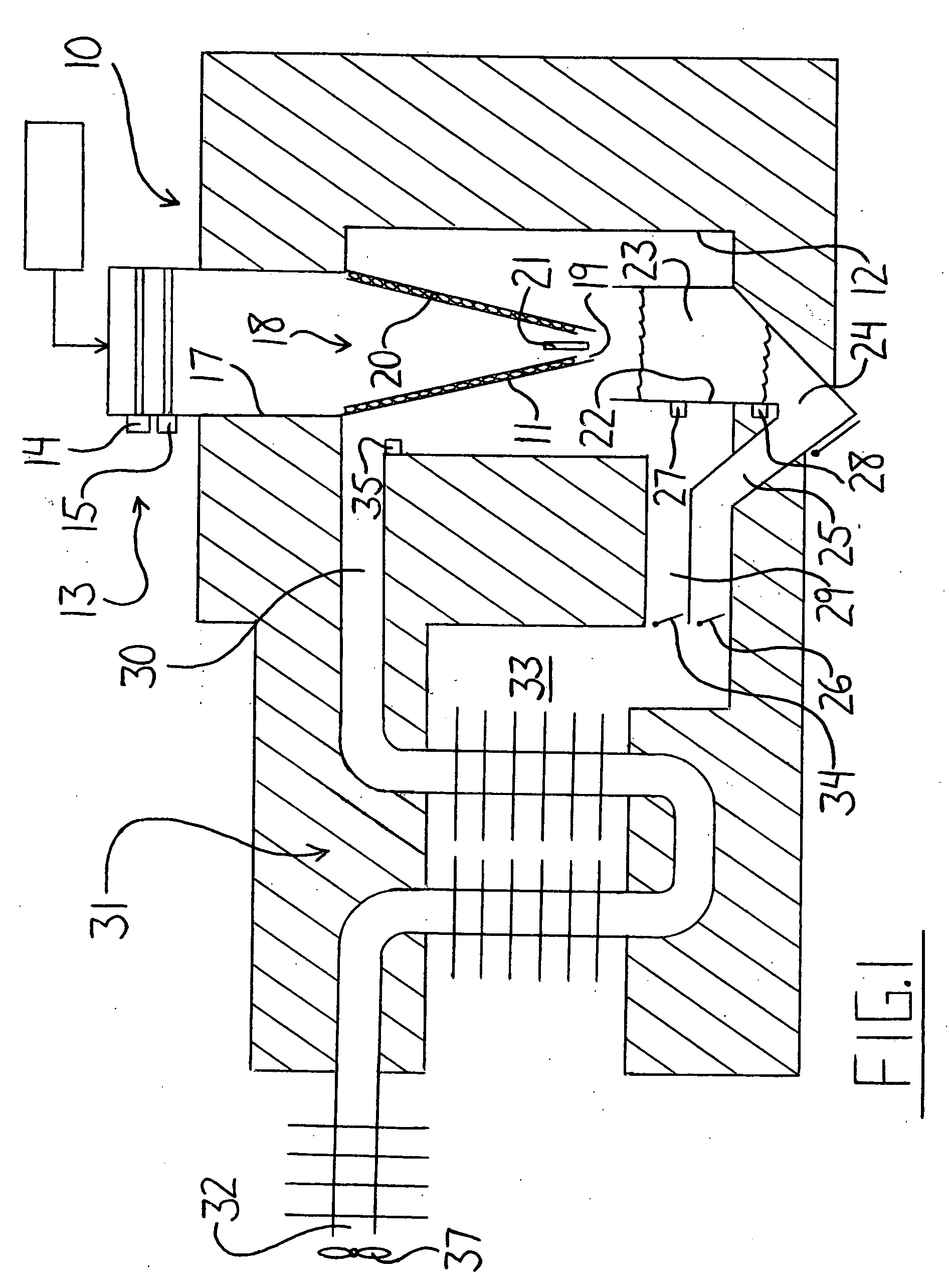
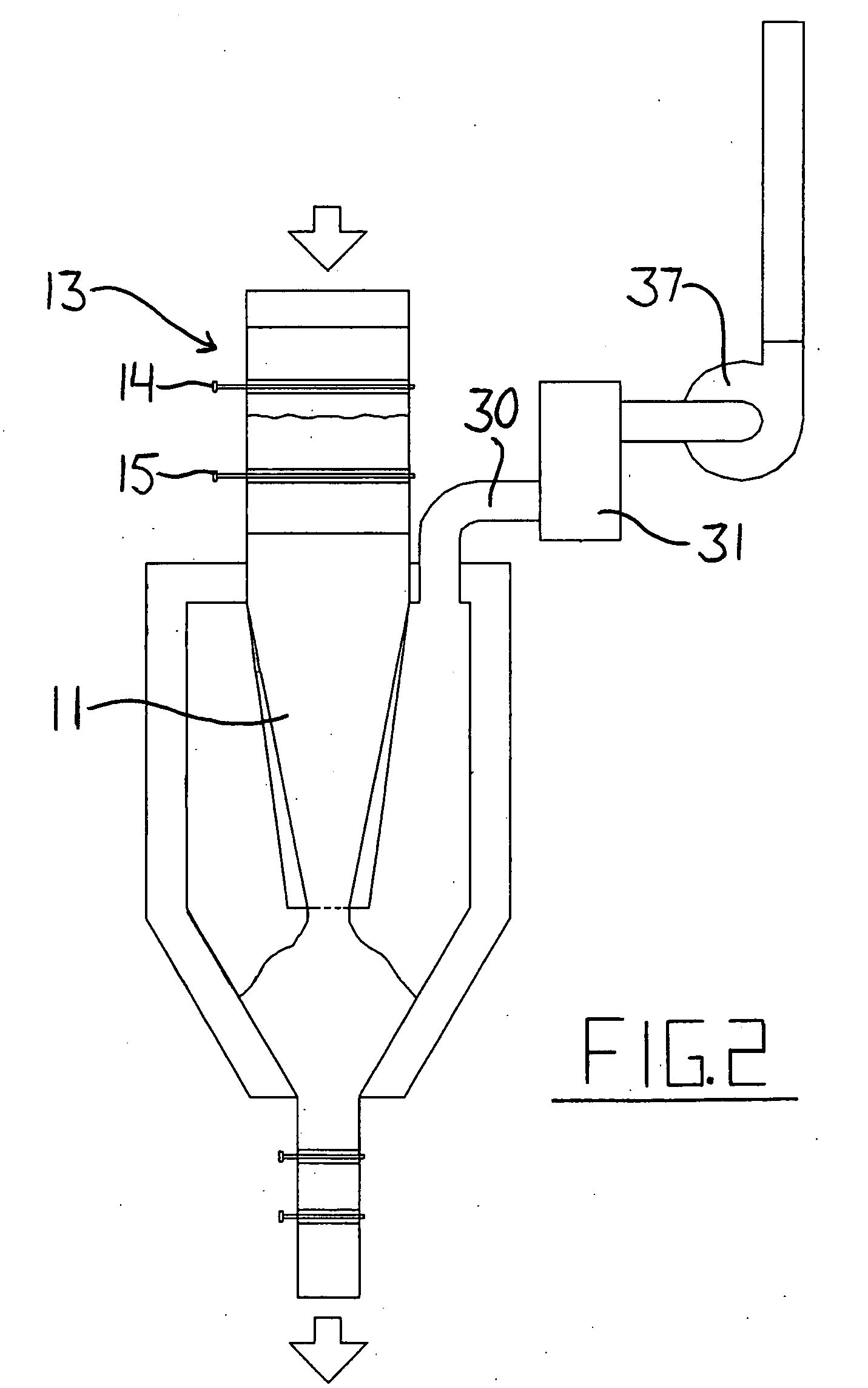
[0091] In FIG. 1 is shown a combustion chamber generally indicated at 10 which includes an interior reaction vessel 11 and an exterior combustion vessel 12 within which the combustion occurs. Feed materials are fed into the reaction vessel 11 by a feeding system generally indicated at 13 which includes an air lock system defined by gates 14 and 15 which can be operated sequentially to allow materials between the gates to be deposited into the reaction vessel 11 for breakdown. A conveyor 16 is provided in the form of an elevator which raises the materials from the ground to the necessary height above the feeding system 13 so that when dropped into the feeding system, the remainder of the operation is effected by gravity through the primary chamber 11 into the exterior chamber 12 without the necessity for any moving elements to carry the fed materials. From the feed system 13, the feed materials are carried through a chute 17 and into the interior of the reaction vessel 11.

[0092] The...


PUM

PropertyMeasurementUnit
temperatureaaaaaaaaaa
retention timeaaaaaaaaaa
temperatureaaaaaaaaaa

Abstract

Break down of waste materials such as animal parts is carried out by pyrolysis, gasification and combustion using a reactor vessel with a conical lower portion located within an exterior vessel. Feed material is deposited in continuous mode through an air lock at the top and falls by gravity alone into the lower cone portion. The cone geometry supports organic feedstocks, eliminating the requirement for grates or other combustion support systems. Organic material that may escape gasification and exit the bottom of the cone accumulates within the ash and carbon particle volume until burned. Carbon is sequestered from high energy feedstocks and is stored in a chamber below the gasification cone. This carbon supplements the energy output of lower energy feedstocks to maintain desired operating temperatures at all times.

Description

[0001] This application claims benefit under 35USC119 of the filing date of Provisional Application 60 / 621,047 filed Oct. 25, 2004.[0002] This invention relates to a method for combustion. The method may be used for breaking down waste materials by pyrolysis, gasification and combustion in a close coupled combustion process. The method disclosed herein may be used for animal waste including deadstock, animals parts, manure and can also be used for other waste organic materials including household, municipal, medical, commercial and hazardous wastes. [0003] The method and apparatus disclosed herein can be used for effectively disposing of deadstock and animal materials while maintaining a temperature sufficient to destroy pathogens including prions. [0004] The method and apparatus disclosed herein can be used to effectively dispose of animal waster material including materials having a moisture content greater than fifty percent with random batches consisting of 100% water (e.g. cont...

Claims


Application Information

Patent Timeline
Patent Type & Authority Applications(United States)
IPC IPC(8): C10G1/00
CPCF23G1/00F23G5/0273F23G5/16F23G2203/403F23G2205/18F23G2206/203F23G2207/101F23G2207/30F23G2209/20F23G2900/50201F23G2900/50204F23J1/06Y02E20/12F23G2900/7003
Inventor GIERCKE, RONALD KEITH
Owner DUNFORD HLDG INC
Why Eureka
Try Eureka