Microscope and method of preventing dew condensation on objective lens

a technology of objective lens and microscope, which is applied in the direction of instruments, optical elements, mountings, etc., can solve the problems of significant degradation of thermal insulation effect, difficult to maintain the temperature of the cell at 37° c, and space inside the incubator is not completely thermally insulated from the outside air. , to achieve the effect of preventing dew condensation

Inactive Publication Date: 2006-05-04
OLYMPUS CORP
View PDF5 Cites 31 Cited by
  • Summary
  • Abstract
  • Description
  • Claims
  • Application Information

AI Technical Summary

Benefits of technology

[0020] A method of preventing dew condensation on an objective lens according to still another aspect of the present invention includes controlling a heater that heats an objective lens having a tip portion with a top lens which is disposed in a high humidity space maintained in a predetermined gas temperature and a relative humidity of 90 to 100% for a culture of a living sample, the objective lens allowing for an observation of the living sample incubated in the high humidity space, so that a surface temperature and an internal temperature of the objective lens are higher than a dew-point temperature and lower than a thermal death point of the living sample.

Problems solved by technology

Here, the space inside the incubator is not completely thermally insulated from outside air.
However, when an immersion objective lens is employed, water or oil is filled between the cover glass and the top lens, whereby the effect of thermal insulation is significantly degraded.
Hence, especially when the temperature of the outside air is low, it is difficult to maintain the temperature of the cell at 37° C.
The techniques as disclosed in the above cited documents have various problems.
Due to the differential temperature here, dew is condensed on the surface of the top lens of the objective lens to cause mist.
When the objective lens employed in the microscope has a high numerical aperture (NA), even a tiny amount of mist causes degradation of microscopic image, hampering a satisfactory observation.
With the structure as described above, however, the objective lens is subjected to an air in high temperature and high humidity leaked out from the cell culture space, and the top lens is easily misted.
When dew is condensed on any of the lenses in the objective lens, the microscopic image is degraded similarly as described above hampering a satisfactory observation.
Then, the air touches the top lens of the objective lens to suddenly cool the objective lens, causing dew condensation from the water vapor accumulated inside the objective lens.
Then, similarly as described above, the microscopic image is degraded and a satisfactory observation becomes unachievable.

Method used


Image

  • Microscope and method of preventing dew condensation on objective lens
  • Microscope and method of preventing dew condensation on objective lens
  • Microscope and method of preventing dew condensation on objective lens

Examples


first embodiment

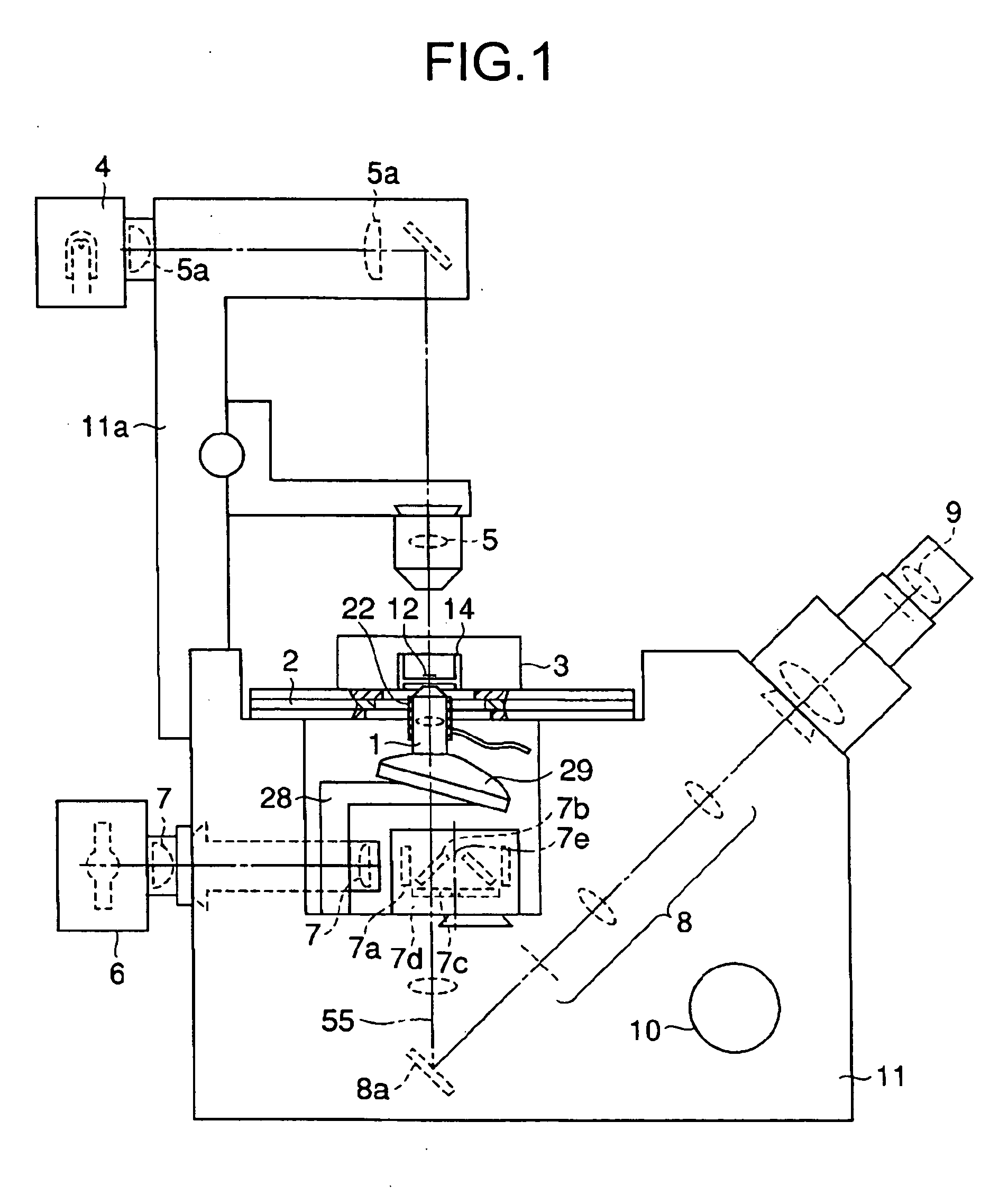
[0028]FIG. 1 shows a schematic structure of an inverted microscope according to the present invention.

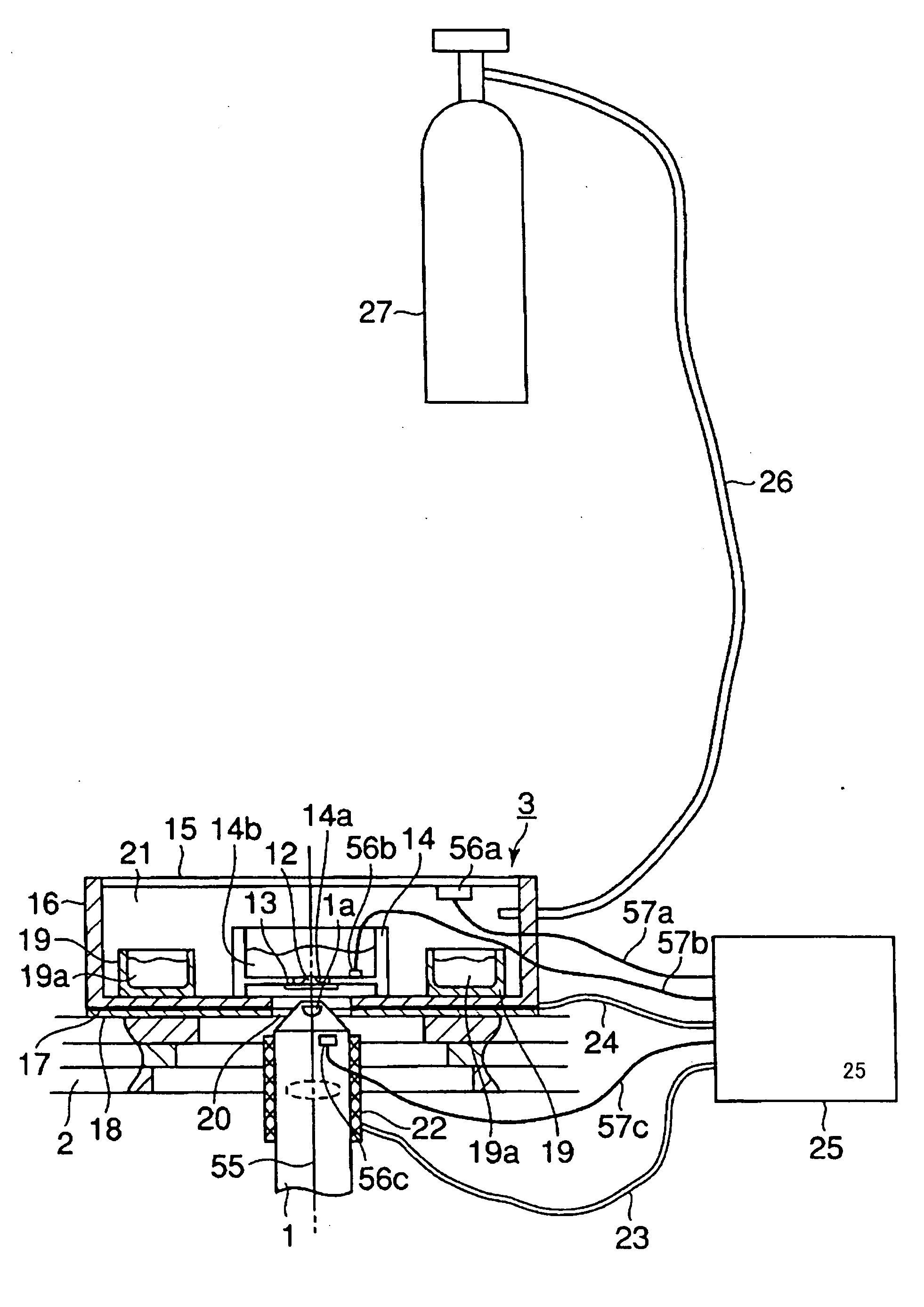
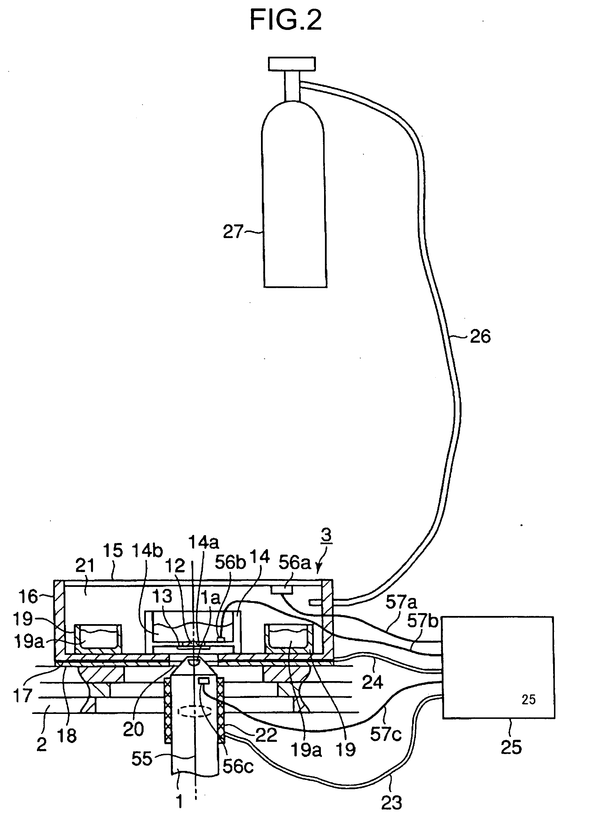
[0029] In FIG. 1, on a main microscope housing 11, a stage 2 is disposed. The stage 2 is horizontally movable along an X-Y direction according to a manipulation of a stage handle (not shown). On the stage 2, a cell incubator 3 containing a cultured cell 12, which is a living sample, is placed. The cell incubator 3 will be described in detail later.

[0030] The main microscope housing 11 has a lighting pillar 11a which faces down to the stage 2. The lighting pillar 11a has a top portion which extends in a substantially horizontal direction forming a substantially right angle with a surface of the stage 2.

[0031] The lighting pillar 11a has a light source 4 for transmissive lighting. The light source 4 may be a halogen lamp, a mercury lamp, or the like. A light beam emitted from the light source 4 passes through an optical path on which a transmissive lighting optical system 5a and a c...

second embodiment

[0058] Next, the present invention will be described.

[0059]FIG. 3 shows a schematic structure of main parts of a microscope according to the second embodiment of the present invention, and the same reference characters are assigned to the same elements shown in FIGS. 1 and 2.

[0060] Here, the objective lens 1 has the top lens 1a and a group of other lenses 1a1 adhesively fixed to an opening of a cylindrical inner frame 1b. The inner frame 1b is fit into a void in a cylindrical middle frame 1d and secured by a holding tube 1c. On an outer periphery of the middle frame 1d, the sheet-like heater 22 having an electrically-heated coil is adhesively fixed. An outer periphery of the heater 22 is covered by an outer frame 1e which is screwed into the middle frame 1d and secured.

[0061] The objective lens 1 with the above-described structure is detachably fixed to the revolver 29 via a threaded portion 1f provided at a lower portion of the outer frame 1e.

[0062] On the other hand, the revolv...

third embodiment

[0082] Next, the present invention will be described.

[0083] In the first and the second embodiments described above, the objective lens 1 in the cell incubator 3 disposed on the stage 2 of the inverted microscope is heated in order to achieve prevention of dew condensation on the objective lens 1. In a microscope with a cell incubator according to the third embodiment, substantially the entire microscope including the objective lens can be heated.

[0084]FIG. 6 shows a schematic structure of main parts of a microscope with a cell incubator according to the third embodiment. The same reference characters are assigned to the same elements as shown in FIG. 2. Here, the microscope with the cell incubator generally has three spaces, i.e.:

[0085] (a) a cell culture space 37 which temperature, humidity and CO2 concentration are controlled;

[0086] (b) an observation space 38 of the microscope including the objective lens 1 in which only temperature is controlled;

[0087] (c) a space 381 provi...


PUM


Abstract

A microscope includes a high humidity space that is maintained at a predetermined gas temperature and a predetermined relative humidity for culture of a living sample; an objective lens having a tip portion with a top lens which is disposed in the high humidity space, and serving to allow for an observation of the living cell incubated inside the high humidity space; a heater that heats the objective lens; and a temperature controller that controls the heater so that a surface temperature and an internal temperature of the objective lens are higher than a dew-point temperature and lower than a thermal death point of the living sample.

Description

CROSS-REFERENCE TO RELATED APPLICATIONS [0001] This application is based upon and claims the benefit of priority from Japanese Patent Application No. 2004-314253, filed Oct. 28, 2004; the entire contents of which are incorporated herein by reference. BACKGROUND OF THE INVENTION [0002] 1. Field of the Invention [0003] The present invention relates to a microscope employed for a cell incubator and a method of preventing dew condensation on an objective lens of such microscope. [0004] 2. Description of the Related Art [0005] In a field of biology and the like, observations of behaviors of living cells of animals and plants, which are kept alive under an appropriate condition, are generally carried out for a functional analysis of a living organism. [0006] A cell incubator is employed to keep the living cell alive under a constant environmental condition for the observation of behavior of the living cell. [0007] One conventional technique for observing a cultured cell which can be kept ...

Claims


Application Information

Patent Timeline
Patent Type & Authority Applications(United States)
IPC IPC(8): G02B21/26
CPCG02B7/008G02B21/30C12M41/36C12M41/12G02B27/0006
Inventor TSUCHIYA, ATSUHIROYAMAGUCHI, KATSUYOSHIKAGAYAMA, AKITSUGUHASEGAWA, KAZUHIROENDO, HIDEAKIKOYAMA, KENICHI
Owner OLYMPUS CORP
Why Eureka
Try Eureka