Backlight unit and liquid crystal display device

a backlight unit and liquid crystal display technology, applied in semiconductor devices, lighting and heating apparatus, instruments, etc., can solve the problems of low color realization ratio of backlight units using related art fluorescent lamps, limited miniaturization and lightness in weight, and difficulty in obtaining backlight units having high luminan

Inactive Publication Date: 2006-05-04
LG DISPLAY CO LTD
View PDF16 Cites 56 Cited by
  • Summary
  • Abstract
  • Description
  • Claims
  • Application Information

AI Technical Summary

Benefits of technology

[0035] Accordingly, the present invention is directed to a backlight unit and an LCD device that substantially obviate one or more problems due to limitations and disadvantages of the related art.

Problems solved by technology

However, the CRT has limitations to miniaturization and lightness in weight due to its big size and heavy weight.
However, the backlight unit of using the related art fluorescent lamp has a low color realization ratio due to the emission characteristics of the light source.
Furthermore, it is hard to obtain the backlight unit having high luminance due to limits in size and capacity of the fluorescent lamp.
However, the fluorescent lamp is problematic in that it requires a noxious gas.
That is, the fluorescent lamp may cause the environmental contamination.
Thus, to obtain the desirable luminance on the entire surface of the LCD panel, it is necessary to increase the power consumption.
Thus, it is impossible to discharge the heat generated from the LEDs 70 to the outside in a short time.
Therefore, it is impossible to achieve the thermal reliability of LED in operation of the LCD device.
If driving the backlight unit for a long time, it is impossible to discharge the heat generated from the LEDs to the outside of the backlight unit in a short time due to the limitation in thermal conduction of aluminum.
Therefore, it is impossible to discharge the generated heat to the outside in a short time.
However, the LED chip has no space for discharging the heat since the reflecting sheet is formed in correspondence with the LED chip.
Therefore, it is difficult to discharge the generated heat to the outside in a short time.
Accordingly, the temperature increases in the junction between each of the LEDs, thereby deteriorating the reliability in operation of the LED.

Method used


Image

  • Backlight unit and liquid crystal display device
  • Backlight unit and liquid crystal display device
  • Backlight unit and liquid crystal display device

Examples


first embodiment

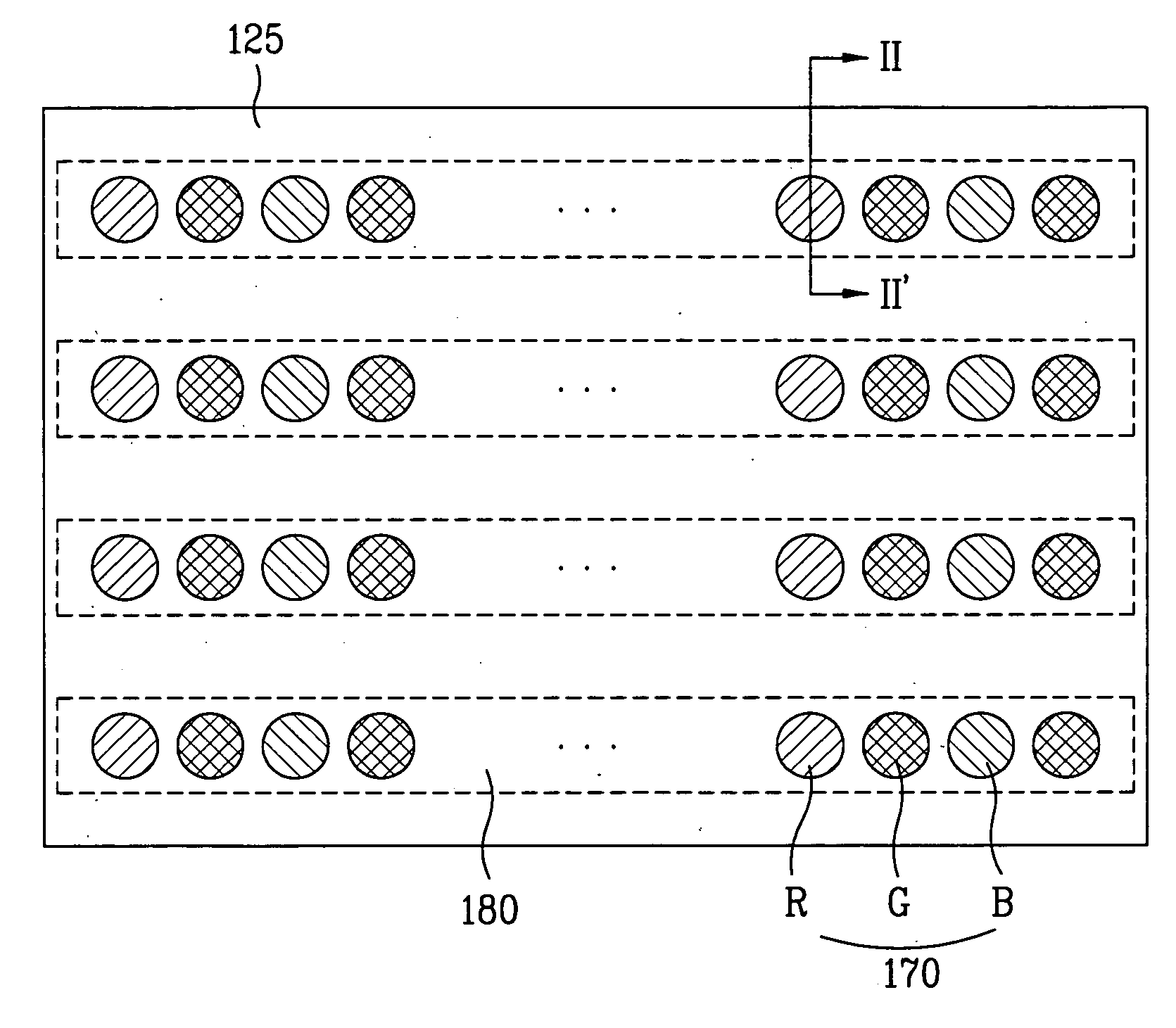
[0062] As shown in FIG. 5, an LCD device including the LED according to the present invention includes the cover bottom 120, the heat pipes 180 the red R, green G and blue B LEDs 170 the optical sheets 150, the LCD panel 140, a guide panel 160, and a case top 130.

[0063] The heat pipes 180 are formed in parallel to one another on the cover bottom 120. Then, the red R, green G and blue B LEDs are positioned at fixed intervals, wherein the red R, green G and blue B LEDs are formed on each of the heat pipes 180. Also, the optical sheets (150 of FIG. 5) are provided on the red R, green G and blue B LEDs. The LCD panel 140 is formed on the optical sheets 150, and the guide panel 150 supports the LCD panel 140 and the optical sheets 150. Then, the case top 130 is provided at an upper edge of the LCD panel 140 and lateral sides of the guide panel 160 and the cover bottom 120.

[0064] In this case, the guide panel 160 has a protruding pattern. The protruding pattern of the guide panel 160 is ...

second embodiment

[0083] In the backlight unit according to the present invention, the heat generated from the LEDs 170 spreads to the up side and down side by the graphite spreader 127. The heat concentrated on a chip of the LED 170 is transmitted to the reflecting sheet 125, an upper side of a lens of the LED 170 and a lower side of the cover bottom (120 of FIG. 11), and is then discharged to the outside therethrough. The graphite spreader 127 has the great heat-diffusion capacity, whereby the heat generated in the inner chip of the LED 170 is diffused to the surroundings for a short time. Also, the heat generated from the LED 170 is diffused to the lower and upper sides of the LED 170 by convention and conduction, thereby maximizing the heat-diffusion.

[0084] In detail, the thermal conduction coefficient of the graphite spreader corresponds to 400 W / mK to 800 W / mK. In comparison to the related art structure of forming PCBs and a cover bottom below a reflecting sheet, the aforementioned structure ac...


PUM


Abstract

A backlight unit and an LCD device are provided, in which an LED (light emitting diode) is used as a light source of the backlight unit, and the heat generated from the LED is rapidly discharged to the outside. The backlight unit includes in one embodiment a cover bottom; at least one heat pipe located on the cover bottom; and a plurality of light sources located on the at least one heat pipe at fixed intervals.

Description

[0001] This Nonprovisional Application claims priority under 35 U.S.C. §119(a) on Patent application No. 10-2004-0087194 filed in Korea on Oct. 29, 2004 and Patent Application No. 10-2005-0016992 filed in Korea on Feb. 28, 2005, the entire contents of which are hereby incorporated by reference. BACKGROUND OF THE INVENTION [0002] 1. Field of the Invention [0003] The present invention relates to a liquid crystal display (LCD) device, and more particularly, to a backlight unit including a light emitting diode (LED) and an LCD device on which the backlight unit is mounted. [0004] 2. Discussion of the Related Art [0005] A Cathode Ray Tube (CRT), one of flat display devices, has been widely used for monitors of devices such as a television, a measuring machine and an information terminal. However, the CRT has limitations to miniaturization and lightness in weight due to its big size and heavy weight. Accordingly, display devices such as a liquid crystal display (LCD) device using an elect...

Claims


Application Information

Patent Timeline
Patent Type & Authority Applications(United States)
IPC IPC(8): F21V7/04
CPCF21Y2101/02G02F1/133603G02F2001/133628F21V29/006F28D15/0233F28D15/04Y10S362/80F21Y2115/10F21V29/51G02F1/133628
Inventor JEONG, IN SUKKIM, GI BINKIM, TAE WOO
Owner LG DISPLAY CO LTD
Why Eureka
Try Eureka