
Sliding bearing assembly and sliding bearing

Inactive Publication Date: 2006-05-04
HITACHI CONSTR MASCH CO LTD
View PDF8 Cites 26 Cited by
  • Summary
  • Abstract
  • Description
  • Claims
  • Application Information

AI Technical Summary

Benefits of technology

[0006] The present invention has been made in view of the above-described problem with the related art, and an object of the present invention is to provide a slide bearing assembly and a slide bearing, which can ensure sliding operation for a longer period in an oilless self-lubricating state even under a situation of sliding at a very low speed or angular motion in a very small stroke.
[0024] (11) In above (7) or (8), preferably, the solid lubricating fine particles have sizes being small enough to prevent clogging of the pores.

Problems solved by technology

However, the related art described above has the following problem.
Accordingly, for example, when the shaft and the bushing slide just several millimeters, i.e., angularly move in a very small stroke, or slide at a very low speed relative to each other, the lubricating effect cannot be developed at a sufficient level.
This may raise local surface pressure and cause local abrasion or damage, such as scratching, in the surface of the shaft or the inner circumference surface of the bushing with accompanying abnormal noise.

Method used


Image

  • Sliding bearing assembly and sliding bearing
  • Sliding bearing assembly and sliding bearing
  • Sliding bearing assembly and sliding bearing

Examples


Embodiment Construction

[0041] Embodiments of a slide bearing assembly and a slide bearing of the present invention will be described below with reference to the drawings.

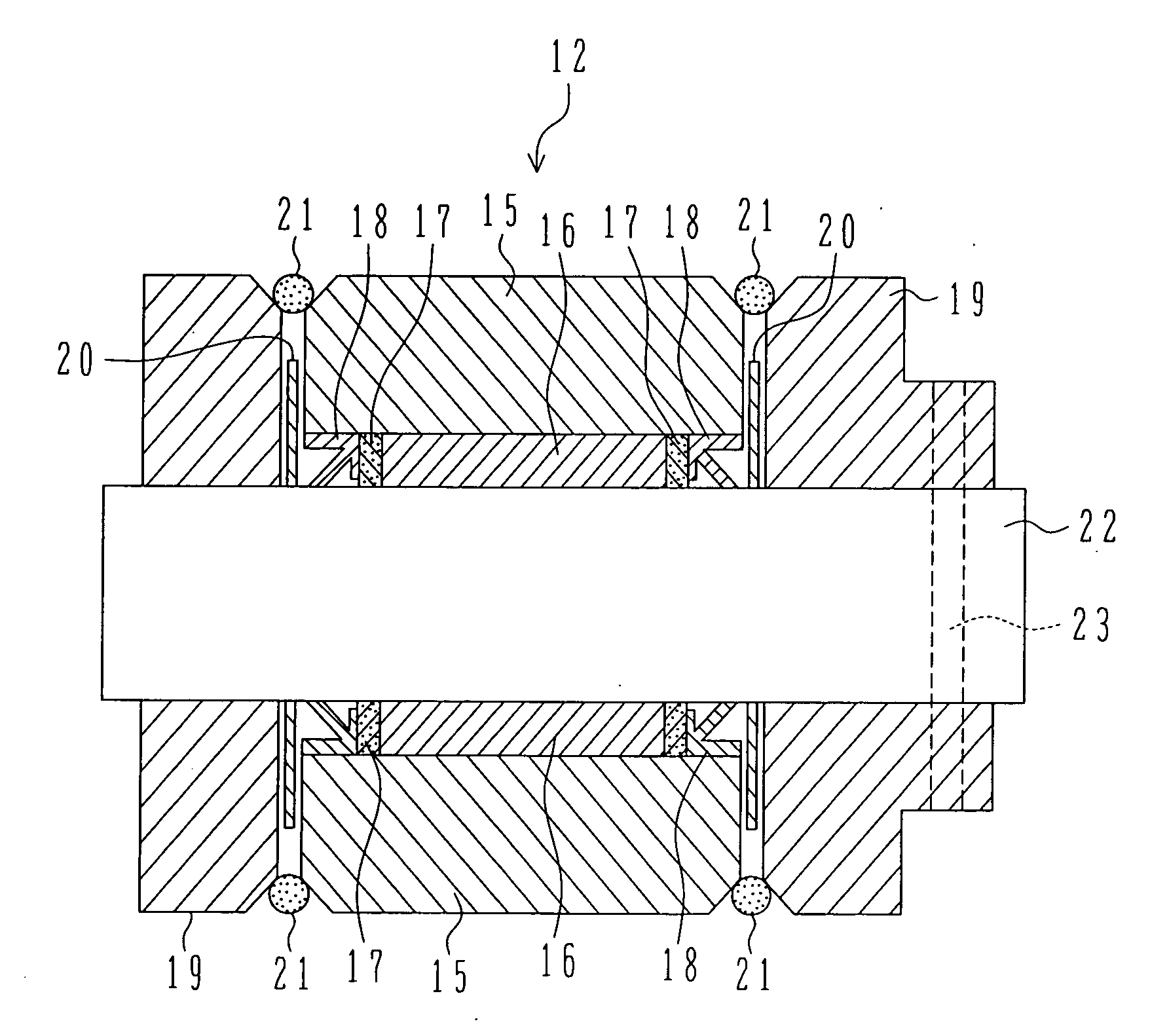
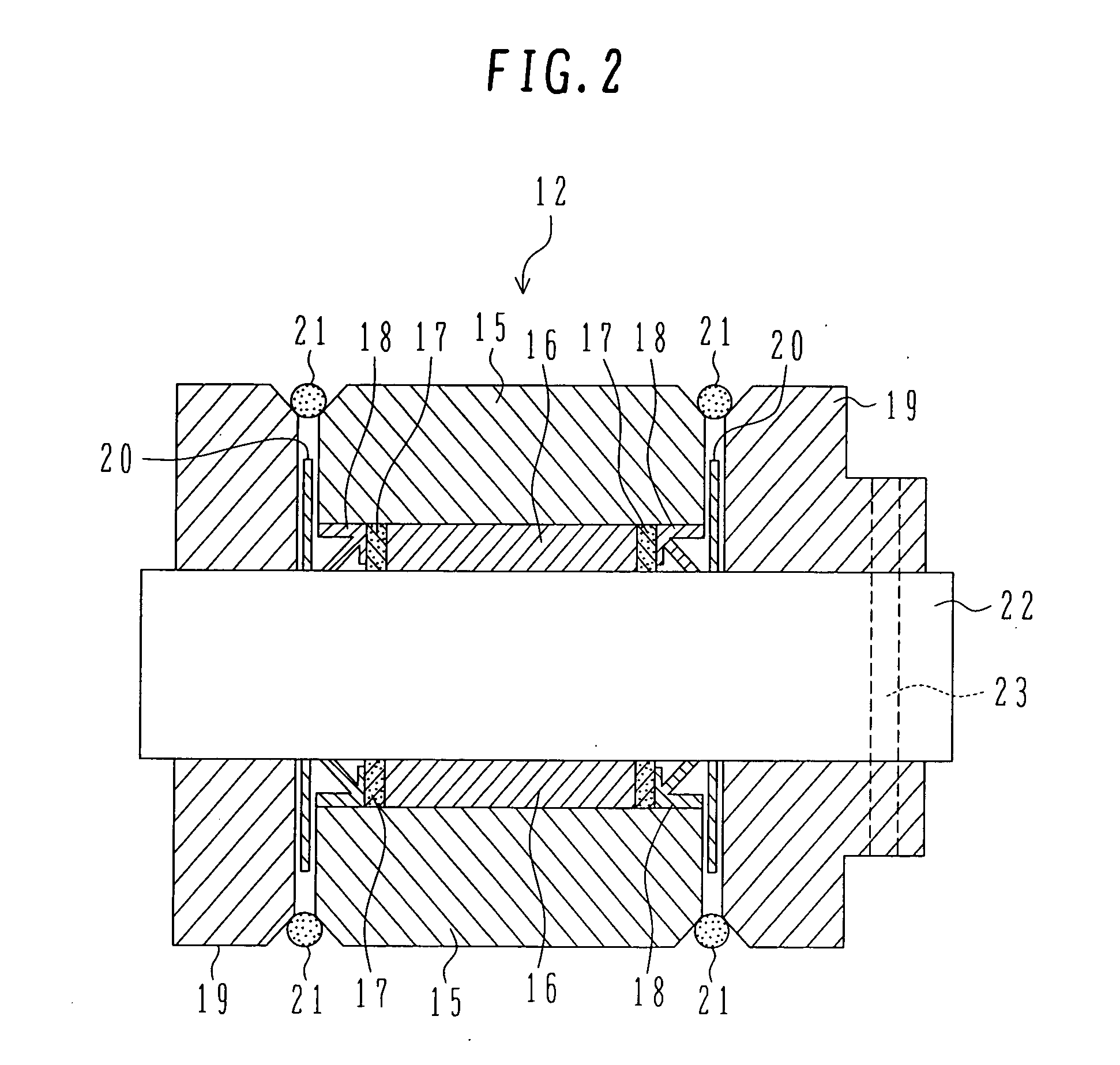
[0042] First, one embodiment of the slide bearing assembly and the slide bearing of the present invention will be described below with reference to FIGS. 1 through 5.

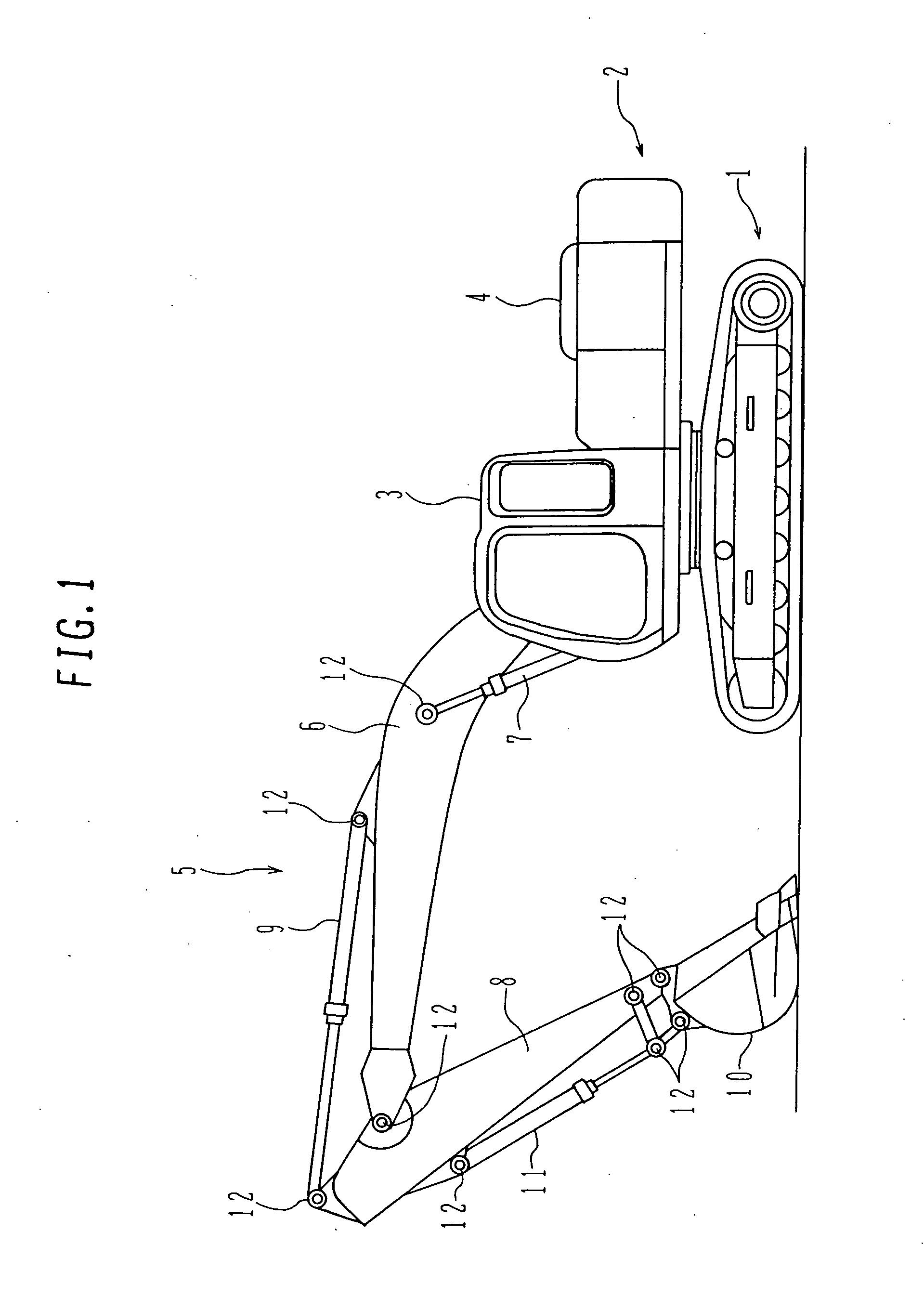
[0043]FIG. 1 is a side view showing an overall structure of a hydraulic excavator equipped with one embodiment of the slide bearing assembly of the present invention.

[0044] In FIG. 1, numeral 1 denotes a travel body, and 2 denotes a swing body mounted on the travel body 1 in a swingable manner. Numeral 3 denotes a cab provided on the swing body 2 at one side (left side as viewed in FIG. 1), 4 denotes an engine room provided on the swing body 2 at the other side (right side as viewed in FIG. 1), and 5 denotes a working device provided on the swing body 2 at the same side as the cab 3. The hydraulic excavator comprises mainly the travel body 1, the swing body 2, the cab 3, t...


PUM


Abstract

In a slide bearing assembly 12 comprising a shaft 22 and a bushing 16 which is made of a porous sintered material having a large number of pores 25, the bushing 16 is impregnated with a lubricant 24 containing 2.0 to 30 wt % of solid lubricating fine particles 26 made of at least one selected from among MoS2, WS2, and hexagonal BN, and the shaft 22 and the bushing 16 are used at surface pressure not lower than 6 Kgf / mm2 and sliding speed in the range of 2 to 5 cm / sec. This realizes prolongation of a period during which sliding operation can be continued in an oilless self-lubricating state even under a situation of sliding at a very low speed or angular motion in a very small stroke.

Description

TECHNICAL FIELD [0001] The present invention relates to a slide bearing assembly and a slide bearing, more particularly to a slide bearing assembly and a slide bearing, which can ensure sliding operation for a longer period in an oilless self-lubricating state even under a situation of sliding at a very low speed or angular motion in a very small stroke. BACKGROUND ART [0002] In an excavator used as a construction machine or the like, to operate a driving mechanism, members constituting the driving mechanism are coupled to each other in a relatively rotatable or angularly movable manner and are driven by cylinders or other actuators. In a working device of a hydraulic excavator, for example, an arm is coupled to a fore end of a boom and a bucket is coupled to a fore end of the arm. During excavation, an arm cylinder and a bucket cylinder are driven to rotate or angularly move the arm about a joint between the arm and the boom and the bucket about a joint between the bucket and the a...

Claims


Application Information

Patent Timeline
IPC IPC(8): F16C33/02E02F9/00F16C11/04F16C33/10F16C33/12
CPCE02F9/006F16C11/045F16C33/109F16C33/104F16C33/12F16C2350/26E02F3/38F16C11/04F16C33/10
Inventor AKITA, HIDEKIGOKITA, OSAMUISOGAI, TORU
Owner HITACHI CONSTR MASCH CO LTD
Features
  • Generate Ideas
  • Intellectual Property
  • Life Sciences
  • Materials
  • Tech Scout
  • Unparalleled Data Quality
  • Higher Quality Content
  • 60% Fewer Hallucinations
Learn More