Flow field design for high fuel utilization fuel cells

Inactive Publication Date: 2006-05-04
GENERAL ELECTRIC CO
View PDF12 Cites 23 Cited by
  • Summary
  • Abstract
  • Description
  • Claims
  • Application Information

AI Technical Summary

Benefits of technology

[0007] This invention seeks to improve overall fuel cell performance by new flow field and flow channel designs. To this end, the invention addresses two requirements of

Problems solved by technology

Flow field uniformity is a critical issue for high performance fuel cells.
The reduction in partial pressures can be drastic, causing the Nernst potential across

Method used


Image

  • Flow field design for high fuel utilization fuel cells
  • Flow field design for high fuel utilization fuel cells
  • Flow field design for high fuel utilization fuel cells

Examples


Embodiment Construction

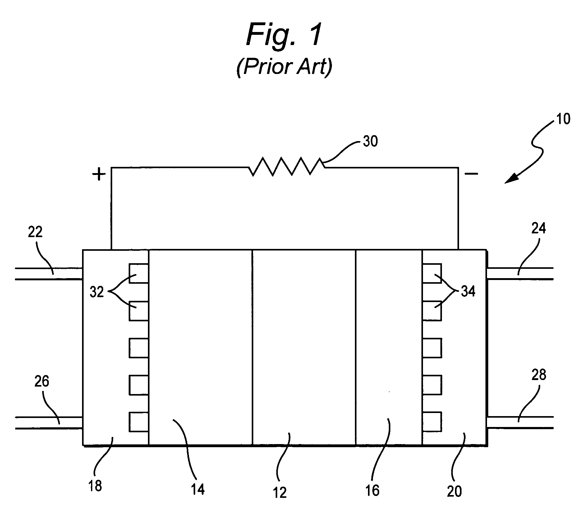
[0031] A schematic diagram of a typical solid oxide fuel cell stack is depicted in FIG. 1. For simplicity, however, FIG. 1 shows only one cell in the stack. The cell 10 comprises an electrolyte-electrode assembly that includes a solid oxide electrolyte 12 sandwiched between a cathode 14 and an anode 16. During operation, oxidant (typically air) and fuel (typically hydrogen) are supplied to flow field plates 18, 20 respectively at inlets 22, 24. The oxidant and fuel streams exhaust from stack 10 at outlets 26, 28. During operation, power is delivered to a load depicted as resistor 30.

[0032] Flow fields are incorporated into distribution or flow channels 32, 34 that are formed in the flow field plates 18, 20 for delivery of reactants directly to surfaces of cathode and anode in the outflow direction.

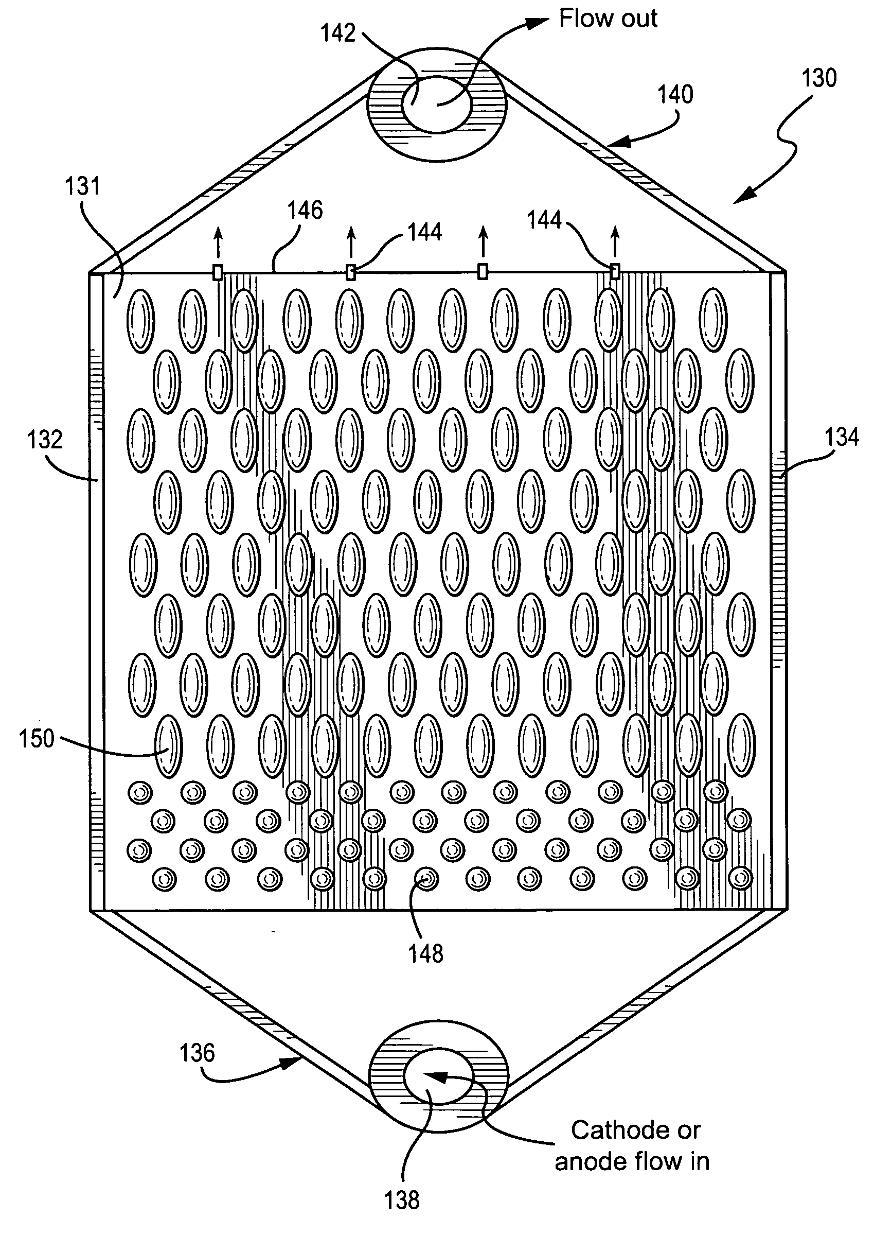
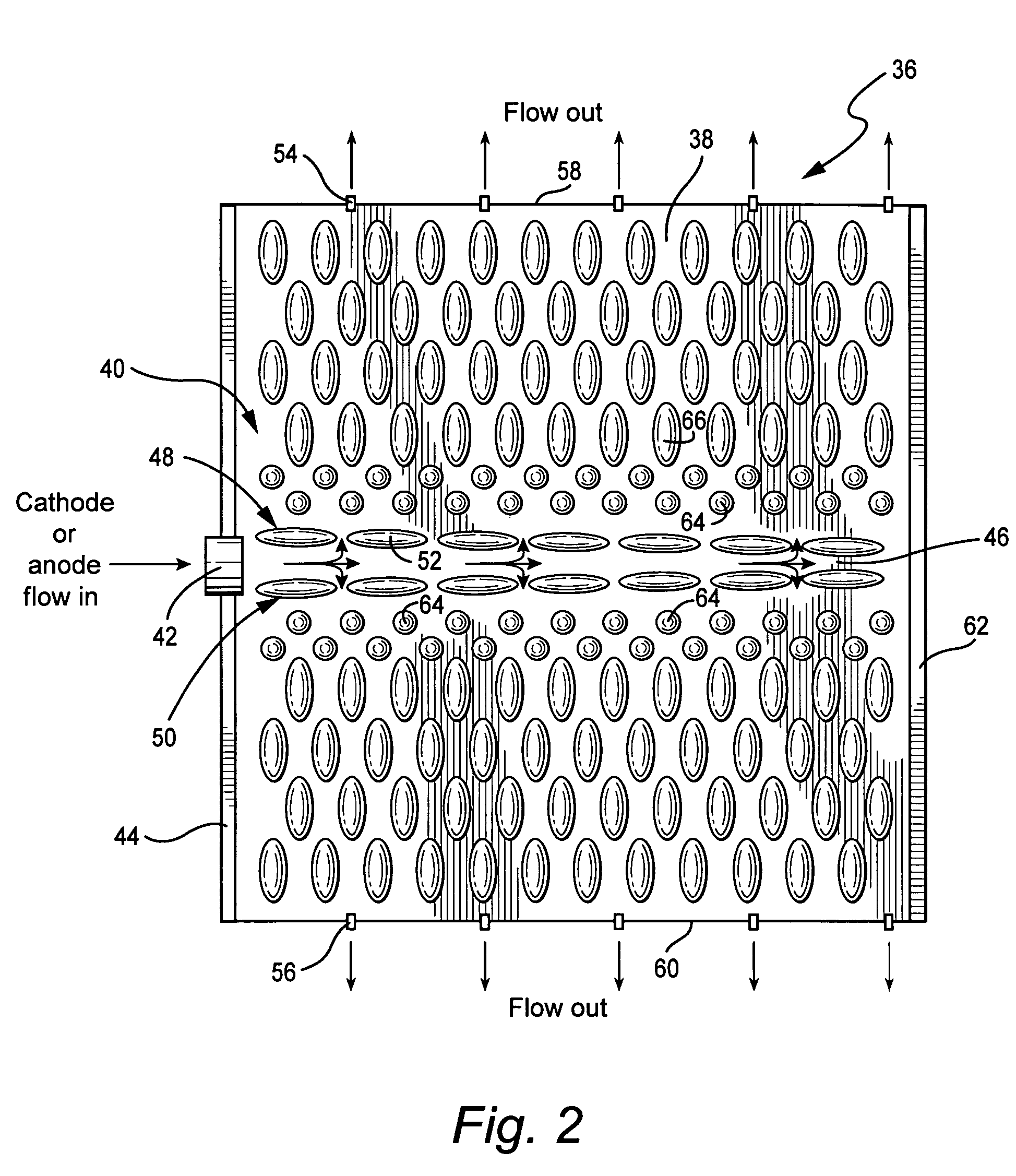
[0033] Referring to FIG. 2, a flow field design for a fuel cell flow channel 36 formed in a flow field plate 18 or 20 is illustrated in schematic form. The flow field 38 includes a flat ...


PUM


Abstract

A flow field forming one wall of a channel in a flow field plate of a solid oxide fuel cell, the flow field includes a flat substrate having a patterned array of differently-shaped flow barriers projecting from the substrate into the channel, the flow field channel decreases in cross-sectional area in a flow direction.

Description

BACKGROUND OF THE INVENTION [0001] This invention relates to high performance fuel cells and, more specifically, to optimized flow field and channel designs for promoting uniform performance and improved efficiency of the fuel cell system. [0002] Fuel cells convert reactants, namely fuel and oxidants, to generate electric power and reaction products. Fuel cells generally employ an electrolyte disposed between two electrodes, namely a cathode and an anode. Preferred fuel cell types include solid oxide fuel cells (SOFCs) that comprise a solid oxide electrolyte and operate at relatively high temperatures. Generally, the SOFC employs an oxygen-ion conductor (such as stabilized zirconia, doped ceria, and doped lanthanum gallate) or proton conductors (such as doped perovskite Ba(Sr)CeO3, Ba(Sr)ZrO3, and mixed perovskites A3(B′B″)O9) as the electrolyte. Currently, SOFCs use almost exclusively oxygen-ion conducting yttria-stabilized zirconia (YSZ) as the electrolyte. [0003] During normal op...

Claims


Application Information

Patent Timeline
IPC IPC(8): H01M8/02
CPCH01M8/0258H01M8/0265H01M2008/1293Y02E60/50Y02E60/525H01M8/2483H01M8/0263H01M8/02
Inventor ISSACCI, FARROKHGUAN, JIEONG, ESTELA T.
Owner GENERAL ELECTRIC CO
Why Eureka
Try Eureka