
Method and apparatus for inhibiting frozen moitsture accumulation in HVAC systems

a technology of hvac system and frozen moitsture, which is applied in the direction of defrosting, heating types, domestic cooling apparatus, etc., to achieve the effect of reducing system operational efficiency and reducing system design efficiency

Inactive Publication Date: 2006-05-11
WIGGS B RYLAND
View PDF12 Cites 18 Cited by
  • Summary
  • Abstract
  • Description
  • Claims
  • Application Information

AI Technical Summary

Benefits of technology

[0012] It is an object of the invention to provide a means to inhibit ice accumulations on system component areas of any refrigerant-based heat transfer system or evaporative cooling system where accumulated frozen moisture, such as frozen humidity, frozen rain, snow, or hail, would decrease system operational design efficiencies for any reason. One such decrease in system operational efficiencies, for example, would be occasioned by the necessity for an air-source heat pump system to operate in a defrost mode.
[0013] This objective is accomplished by means of applying a non-stick coating to the exterior portion of any refrigerant-based or evaporative cooling based heating or cooling system where undesirable ice accumulation could occur. The non-stick coating will prevent ice from adhering to the exterior finned heat transfer tubing, or to any other air-exposed system surface areas desired. In turn, this will provide advantages such as eliminating the need for a defrost or a de-icing cycle, thereby increasing system operational efficiencies and decreasing system operational costs.
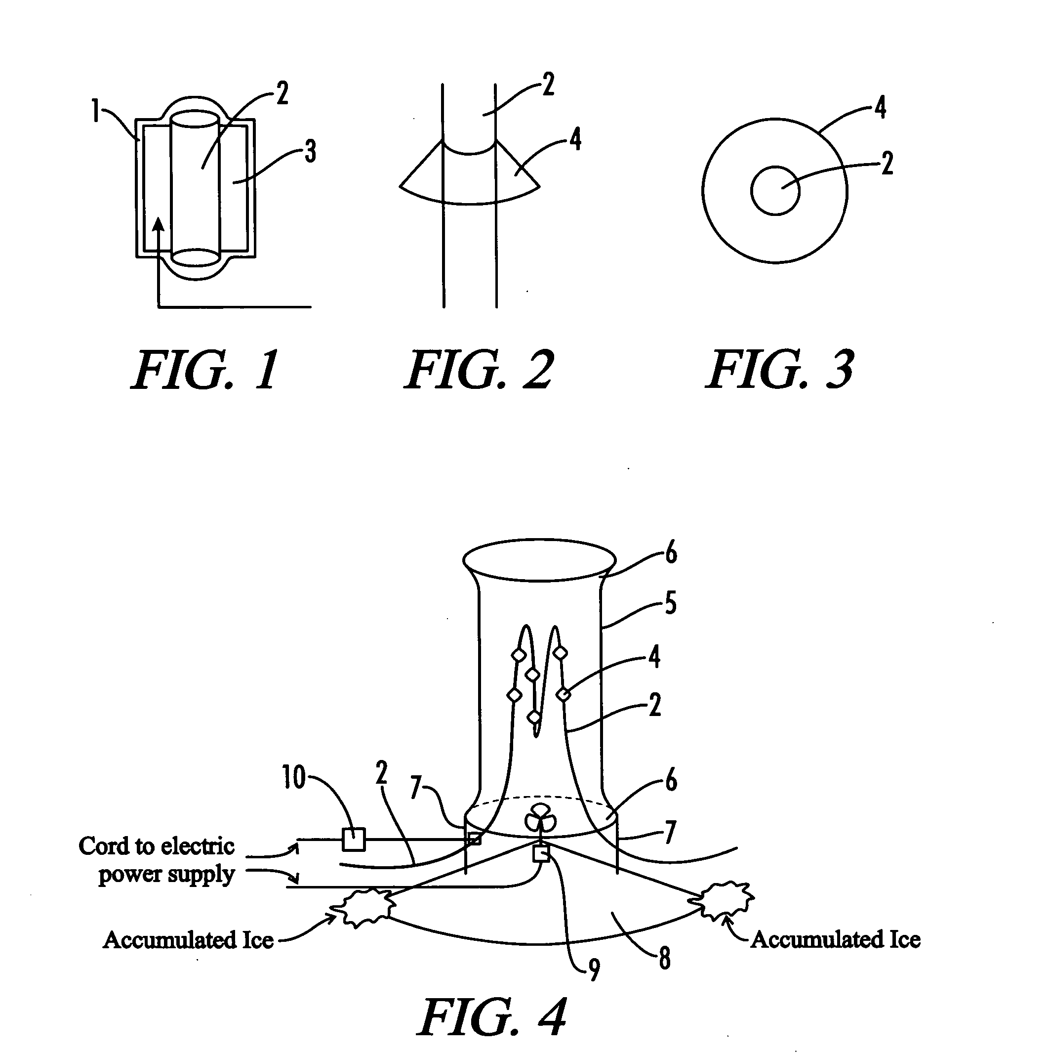
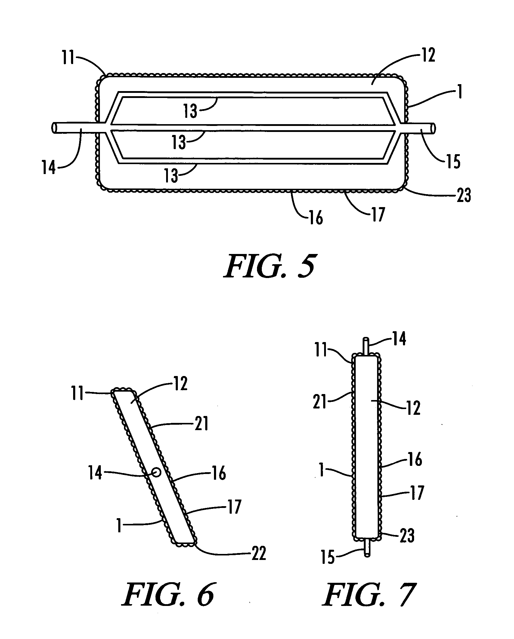
[0017] To achieve a more reliable ice removal method, in conjunction with the non-stick surface coating, a fin design should be utilized whereby the fins are sloped, or are spiraled, downwardly, or are in a vertical position such that the fins extend in a substantially parallel direction to the longitudinal axis of the tubes transporting the refrigerant fluid, so that gravity alone will pull off any ice forming on the non-stick surface.
[0019] By applying a non-stick coating to the exterior air heat exchange unit, with an appropriately sized and / or with an oversized (oversized from present customary sizing) array of downwardly or vertically sloped fins and / or plates, which fins and / or plates serve to increase the surface area exposed to the air, the electric fan on a conventional air-source heat pump system can be either reduced in size or eliminated on the exterior air heat exchange unit, thereby creating enhanced operational efficiencies. The sizing of the exterior air heat exchange unit fins, plates, or the like, necessary to at least one of reduce the size of conventional system exterior fans and to eliminate the exterior fans altogether is well understood by those skilled in the art.
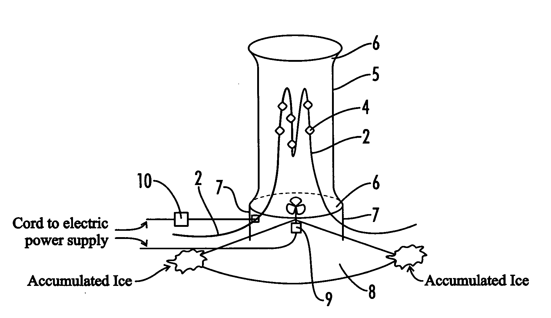
[0020] In such an enhanced efficiency design, the non-stick coated finned tubing and / or plates in the exterior air heat exchange unit may be surrounded with a protective shell, which would also be coated with a non-stick coating, with flared openings at the top and at the bottom so as to create a natural vena contracta effect. Thus, as the heat is transferred into the exterior air in the cooling mode, since hot air rises, the natural upward flow will pull cooler outside air in from the bottom, thereby creating a natural air flow over the non-stick coated finned tubing. In the heating mode, since air from which heat is extracted becomes cooler and heavier, the cooled air will naturally fall and will pull warmer air in from the top, again creating a natural air flow. Because of this naturally induced air flow, the conventionally used electric fan can be either eliminated or reduced in size, thereby increasing system operational efficiencies.
[0021] The exterior non-stick coated air heat exchange unit must be sufficiently elevated so as to allow falling ice to accumulate underneath the unit without building up from below so as to hamper the heat exchange ability of the refrigerant system. Further, the exterior unit should be furnished with a non-stick coated downwardly sloped base, cone-shaped base, or the like, so falling ice will slide harmlessly to the side, at a sufficient distance away from the unit to avoid any airflow obstruction or any other decrease in system operational efficiencies. Additionally, the exterior unit may be equipped with an optional vibrator, which may be programmed to periodically vibrate the finned heat exchange tubing as appropriate, to further enhance the ability of the non-stick surface coating to remove any ice, or other frozen moisture, build-up. The electrical power required to periodically operate a relatively small vibrator is significantly less than the power required by a conventional defrost cycle.

Problems solved by technology

However, some minor insulating properties of the non-stick surface coating will typically more than offset the efficiency losses associated with a de-frost cycle.

Method used


Image

  • Method and apparatus for inhibiting frozen moitsture accumulation in HVAC systems
  • Method and apparatus for inhibiting frozen moitsture accumulation in HVAC systems
  • Method and apparatus for inhibiting frozen moitsture accumulation in HVAC systems

Examples


Embodiment Construction

[0036] A method and apparatus for inhibiting condensation ice accumulation on heat transfer systems, including refrigerant-based heating and cooling systems, and on an evaporative cooling system, according to the invention, utilizes a non-stick coating applied to heat exchange components and other exterior surface areas of the refrigeration system where ice accumulation is not desirable because such ice decreases overall system operational efficiencies. Additionally, according to the invention, certain optional designs for outdoor air heat exchange means, and an optional vibrator, enhance the ability to eliminate condensation ice build-up.

[0037] The following detailed description is of the best presently contemplated mode of carrying out the invention. The description is not intended in a limiting sense, and is made solely for the purpose of illustrating the general principles of the invention. The various features and advantages of the present invention may be more readily underst...


PUM


Abstract

A non-stick coating, which inhibits frozen moisture accumulation, is applied to exterior exposed portions of heating and cooling systems where ice or other frozen moisture can accumulate and impair system design operational efficiencies; where heat exchange tubing and fins are downwardly sloped or angled; where an optional capillary tube / plate means / design, which plate has an exterior surface that is comprised of at least one of raised dots, ridges, trenches, and a flat surface is utilized; with an optional protective shell encasement which can be shaped to provide a vena contracta effect; with an optional electric fan to enhance airflow for heat exchange; with an optional electric vibrator to enhance inhibition of frozen moisture accumulation; with a downwardly sloped base to direct falling frozen moisture away from the heat exchange equipment; for use in conjunction with an air source heat pump system, an evaporative cooling system or a chiller, or as a supplement to a water-source heat pump system or to a direct expansion heat pump system; and for use with any other refrigerant-based heating system or cooling system.

Description

CROSS-REFERENCES TO RELATED APPLICATIONS [0001] This application is a Continuation-In-Part application which claims benefit of co-pending U.S. patent application Ser. No. 10 / 073,515 filed Feb. 11, 2002, entitled “Method And Apparatus for Inhibiting Ice Accumulations in HVAC Systems” and continuation-in-part application filed Oct. 14, 2005, entitled “Capillary Tube / Plate Refrigerant / Air Heat Exchanger for Use in Conjunction with a Method and Apparatus for Inhibiting Ice Accumulation in HVAC Systems” which is incorporated herein by reference.[0002] A portion of the disclosure of this patent document contains material that is subject to copyright protection. The copyright owner has no objection to the facsimile reproduction by anyone of the patent document or the patent disclosure, as it appears in the Patent and Trademark office patent file or records, but otherwise reserves all copyright rights whatsoever. STATEMENT REGARDING FEDERALLY SPONSORED RESEARCH OR DEVELOPMENT [0003] Not App...

Claims


Application Information

Patent Timeline
IPC IPC(8): F24H3/00F25D21/10F25D21/00F25D21/04F28F19/00
CPCF25D21/04F28F19/006F24F2013/221
Inventor WIGGS, B. RYLAND
Owner WIGGS B RYLAND
Learn More