Double-wall pipe, method of manufacturing the same and refrigerant cycle device provided with the same
- Summary
- Abstract
- Description
- Claims
- Application Information
AI Technical Summary
Benefits of technology
Problems solved by technology
Method used
Image

Examples
first embodiment
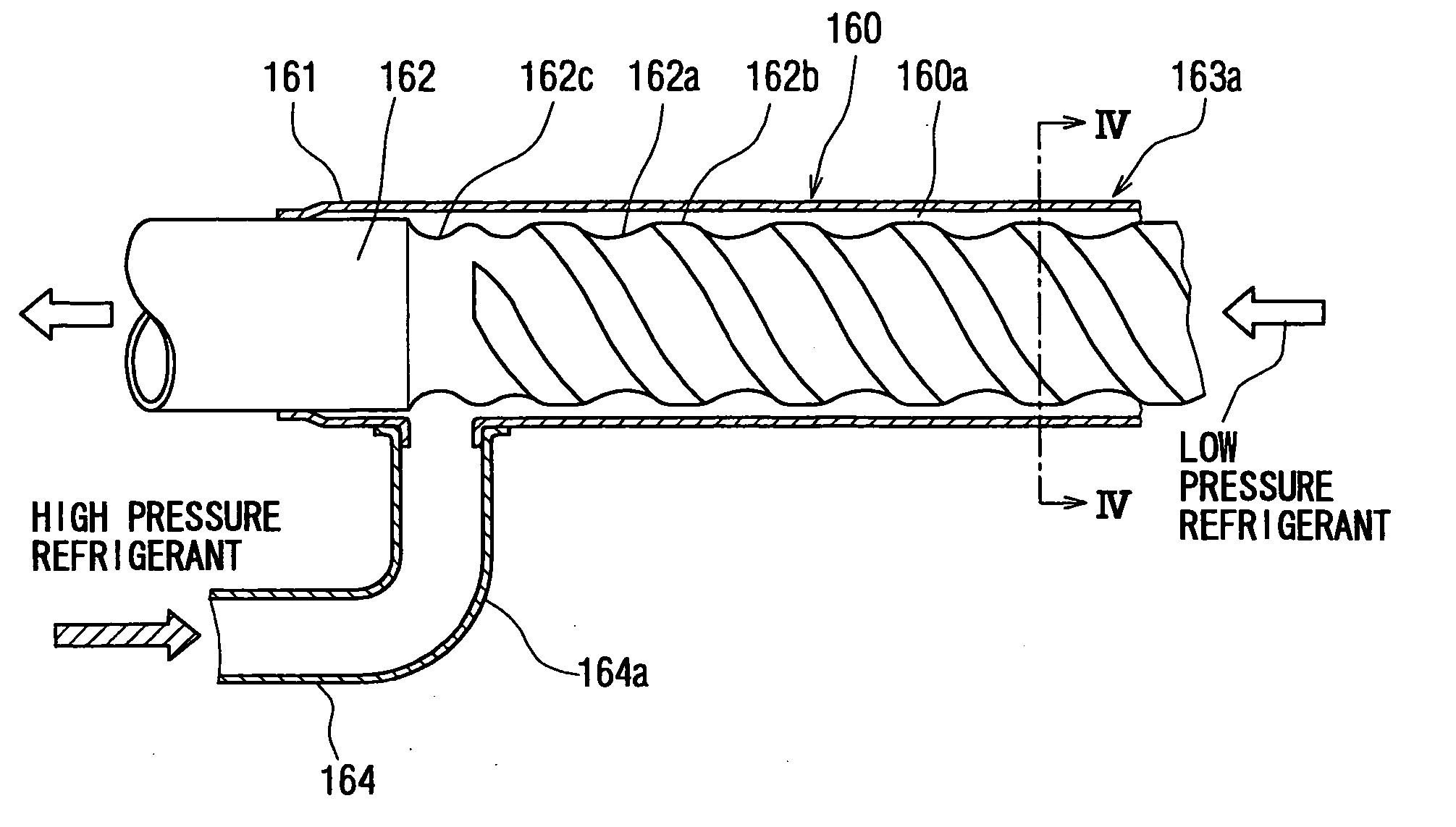
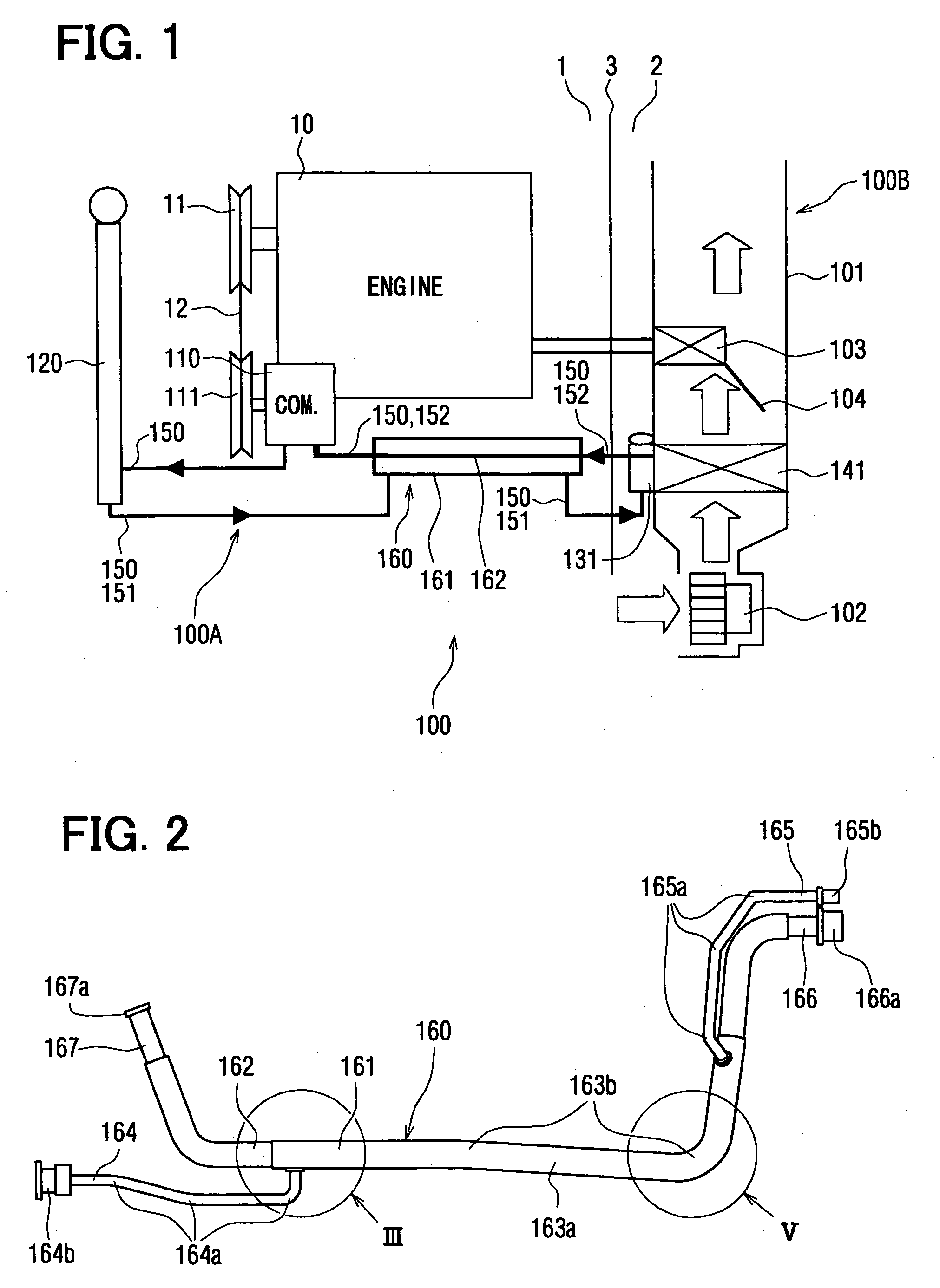
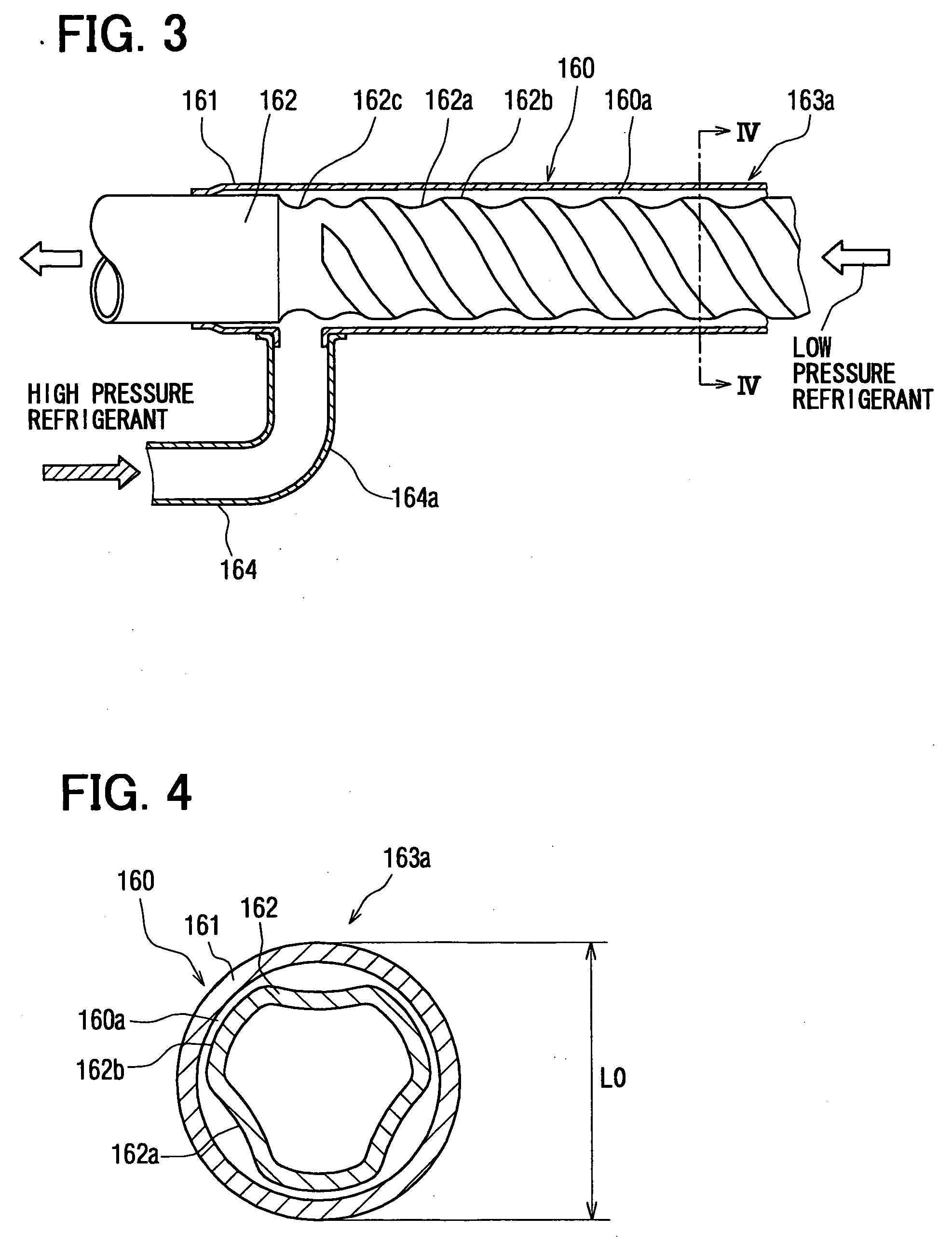
[0040] A double-wall pipe 160 in a first embodiment according to the present invention is typically used for a refrigerant cycle device 100A of a vehicle air conditioning system 100. The double-wall pipe 160 will be described with reference to FIGS. 1 to 5. FIG. 1 is a schematic view of the air conditioning system 100, FIG. 2 is a view of the double-wall pipe 160, FIG. 3 is a sectional view of a part III of the double-wall pipe 160 in FIG. 2, FIG. 4 is a cross-sectional view showing a straight part 163a, FIG. 5 is a sectional view showing a bend portion 163b in FIG. 2, FIG. 6 is a cross-sectional view of a bend portion 163b, and FIG. 7 is a perspective view of a grooving device 200 for forming helical grooves 162a in an inner pipe 162.
[0041] A vehicle has an engine room 1 holding an engine 10 therein and a passenger compartment 2 separated from the engine room 1 by a dash panel 3. The air conditioning system 100 has the refrigerant cycle device 100A including an expansion valve 131...
second embodiment
[0080] A double-wall pipe 160 in a second embodiment according to the present invention will be described with reference to FIGS. 13A and 13B. The double-wall pipe 160 in the second embodiment includes a holding member 168. The holding member 168 fixedly holds end parts of a liquid tube 165 and a suction tube 166 in a predetermined positional relation.
[0081] As shown in FIG. 13A, the holding member 168, similarly to the liquid tube 165 and the suction tube 166, is made of aluminum. The holding member 168 is fastened to the liquid tube 165 and the suction tube 166 by blazing or staking.
[0082] The end parts of the liquid tube 164 and the suction tube 166 fixedly held by the holding member 168 are unmovable relative to each other. Consequently, the liquid tube 164 and the suction tube 166 can be easily connected to the expansion valve 131 and the evaporator 141, respectively.
[0083] As shown in FIG. 13B, a holding member 168A made of a resin may be used. The holding member 168A can b...
third embodiment
[0084]FIG. 14 shows a double-wall pipe 160 in a third embodiment according to the present invention. The double-wall pipe 160 in the third embodiment can be used for a refrigerant cycle device 100A of a dual air conditioning system provided with an evaporator for a rear area in a passenger compartment of a vehicle.
[0085] The refrigerant cycle device 100A includes a first circuit including a first expansion valve 131 and a first evaporator 141 (first low-pressure heat exchanger), and a second circuit including a second expansion valve 132 and a second evaporator 142 (second low-pressure heat exchanger). The first circuit and the second circuit are connected in parallel by using a bypass passage 153 through which refrigerant flows while bypassing the first evaporator 141 and the first expansion valve 131. The bypass passage 153 is connected to the first circuit at a branching point A and a joining point B, so as to form the second circuit. A condenser 120 includes a condensing unit 1...
PUM
| Property | Measurement | Unit |
|---|---|---|
| Length | aaaaa | aaaaa |
| Length | aaaaa | aaaaa |
| Length | aaaaa | aaaaa |
Abstract
Description
Claims
Application Information
 - R&D
- Intellectual Property
- Life Sciences
- Materials
- Tech Scout
- Unparalleled Data Quality
- Higher Quality Content
- 60% Fewer Hallucinations
Browse by: Latest US Patents, China's latest patents, Technical Efficacy Thesaurus, Application Domain, Technology Topic, Popular Technical Reports.
© 2025 PatSnap. All rights reserved.Legal|Privacy policy|Modern Slavery Act Transparency Statement|Sitemap|About US| Contact US: help@patsnap.com