Digital video data transmission system and method

a digital video and data transmission technology, applied in the field of digital video data transmission systems, can solve the problems of increasing electromagnetic wave interference between digital video data lines which constitute the bus, large power consumption of the interface device, etc., and achieve the effect of reducing power consumption and electromagnetic interference, and shortening the hammering distan

Inactive Publication Date: 2006-05-11
SAMSUNG ELECTRONICS CO LTD
View PDF1 Cites 15 Cited by
  • Summary
  • Abstract
  • Description
  • Claims
  • Application Information

AI Technical Summary

Benefits of technology

[0034] The digital video data transmission system and digital video data transmission method perform bit-inversion coding on digital video data having spatial data locality so as to shorten a Hamming distance according to differential values of data adjacent to digital video data, and transmit the bit-inversion coded digital video data to the bus. As a result, as the number of transition of bits included in the digital video data transmitted through the bus decreases, power consumption and electromagnetic interference decrease.

Problems solved by technology

The interface device consumes a lot of power.
Therefore, electromagnetic wave interference between digital video data lines which constitute the bus increases.

Method used


Image

  • Digital video data transmission system and method
  • Digital video data transmission system and method
  • Digital video data transmission system and method

Examples


Embodiment Construction

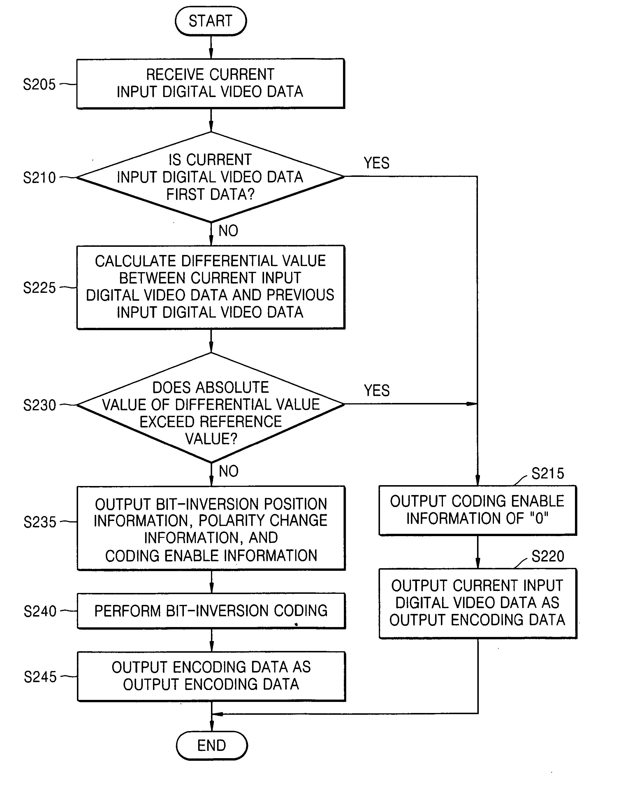
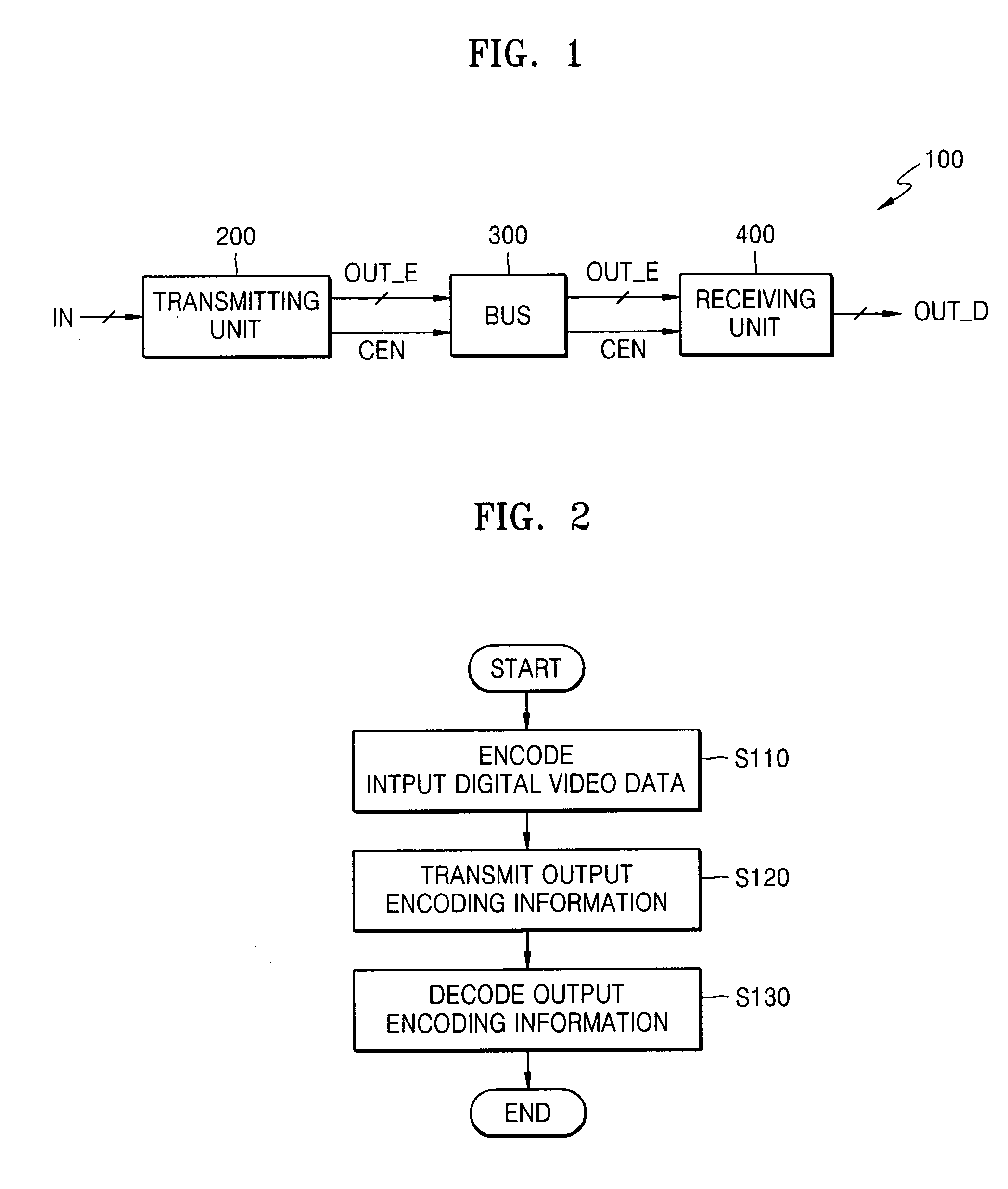
[0046]FIG. 1 is a block diagram illustrating a digital video data transmission system according to an embodiment of the present invention. Referring to FIG. 1, the digital video data transmission system 100 comprises a transmitting unit 200, a bus 300, and a receiving unit 400.

[0047] Digital video data IN are consecutively input in the transmitting unit 200 by an image processing unit (not shown) such as a video controller. Each of digital video data IN constitutes a single image (or frame) background. Differential values between adjacent digital video data IN are relatively small, which is referred to as spatial locality of video data.

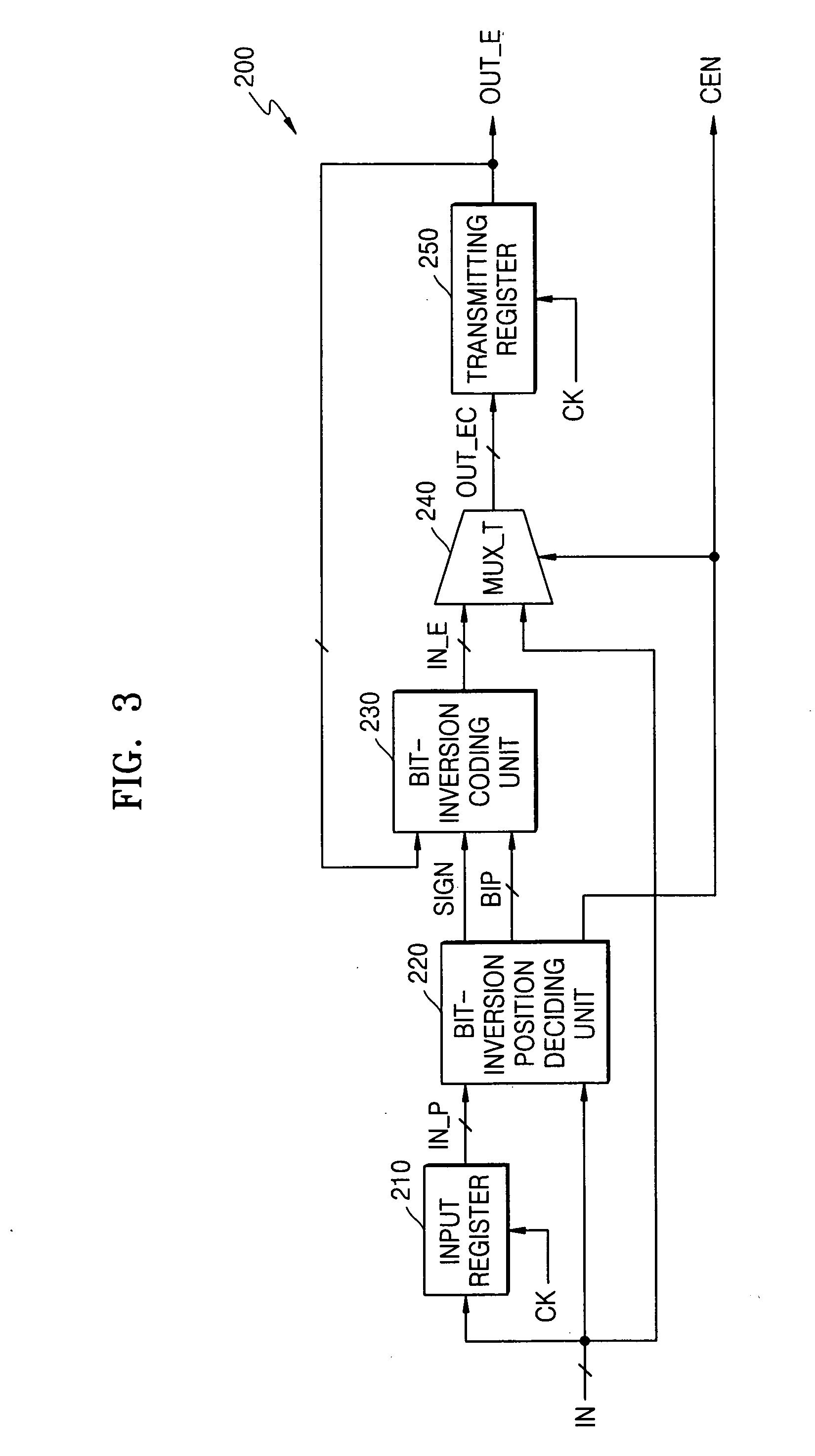
[0048] The transmitting unit 200 transmits valid first data (first data) in input digital video data IN having spatial locality to the bus 300 as output encoding information OUT_E, CEN without bit-inversion coding the first data. The transmitting unit 200 bit-inversion codes previous data of output encoding data OUT_E corresponding to input digital ...


PUM


Abstract

Provided are a digital video data transmission system and digital video data transmission method. The digital video data transmission system includes a transmitting unit transmitting valid first data in input digital video data having spatial locality to a bus as output encoding information without bit-inversion coding the first data, bit-inversion coding previous data of output encoding data corresponding to the input digital video data based on differential values of adjacent digital video data, and transmitting the bit-inversion coded value to the bus as the output encoding information; and a receiving unit not decoding output encoding information transmitted in parallel through the bus, i.e., the first data, but decoding output encoding information transmitted in parallel through the bus based on the differential values. The output encoding information includes the output encoding data and coding enable information that indicates whether to bit-inversion encode previous data of the output encoding data. The digital video data transmission system and digital video data transmission method can reduce the number of transitions of bits included in the digital video data transmitted through the bus, thereby reducing power consumption and electromagnetic interference.

Description

BACKGROUND OF THE INVENTION [0001] This application claims the priority of Korean Patent Application No. 10-2004-89694, filed on Nov. 5, 2004, in the Korean Intellectual Property Office, the contents of which are incorporated herein in their entirety by reference. [0002] 1. Field of the Invention [0003] The present invention relates to a digital video data transmission system, and more particularly, to a digital video data transmission system and digital video data transmission method using spatial locality of video data. [0004] 2. Description of the Related Art [0005] A conventional digital video data transmission system comprises an image processing unit such as a video controller, a transmitting unit, a receiving unit, a bus that connects the transmitting unit and the receiving unit, and a display device such as a liquid crystal display (LCD) panel. A conventional digital video data transmission system is disclosed in U.S. Patent Laid-Open Publication No. 2003-0043141. [0006] The...

Claims


Application Information

Patent Timeline
Patent Type & Authority Applications(United States)
IPC IPC(8): H03M7/00H04B1/66
CPCH03M5/04H03M7/3002H04N21/2343H04N21/4402
Inventor BAE, CHEON-HO
Owner SAMSUNG ELECTRONICS CO LTD
Why Eureka
Try Eureka