Vibration machining device and vibration machining method

a technology of vibration machining and machining method, which is applied in the direction of turning machine accessories, manufacturing tools, printed circuits, etc., can solve the problems of reducing the machining efficiency, reducing the machining time, and so as to reduce the load of the blade edge and reduce the machining time. , the effect of preventing the breakage of cutting tools

Inactive Publication Date: 2006-05-11
DENSO CORP
View PDF10 Cites 31 Cited by
  • Summary
  • Abstract
  • Description
  • Claims
  • Application Information

AI Technical Summary

Benefits of technology

[0061] According to the method for manufacturing an ejector for refrigerating cycle of the present aspect, the cutting tool is prevented from being broken and machining efficiency is improved...

Problems solved by technology

Machining of such a small diameter and small angle tapered deep hole has brought about a problem that the blade edge of a taper-shaped tool may be broken in relation to a thrust force when the blade edge bites a machined workpiece, because the hole has a small taper angle.
If the advancing speed of a tool is reduced in order to prevent the biting phenomenon, the machining efficiency is considerably reduced.
There has been a problem that it takes time to machine a small diameter and small angle tapered deep hole such as an ejector nozzle described above, and reduction in the machining time has been required.
Howev...

Method used


Image

  • Vibration machining device and vibration machining method
  • Vibration machining device and vibration machining method
  • Vibration machining device and vibration machining method

Examples


first embodiment

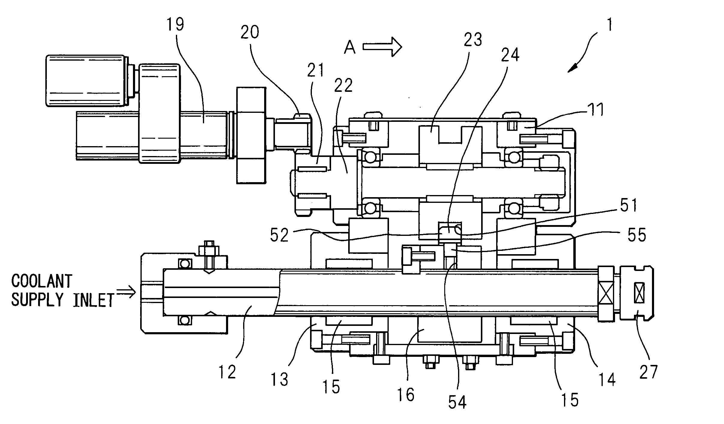
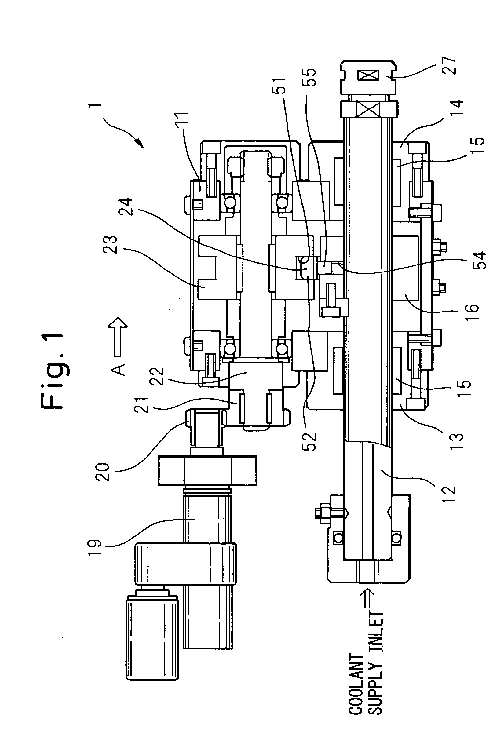
[0080] Referring to FIG. 1 first, a vibration machining device 1 for a small diameter and small angle tapered deep hole that enables small diameter and small angle tapered deep hole machining, that is, the vibration machining device in the present invention, is shown. The vibration machining device 1 comprises a vibration spindle 12, a vibration cam 23, and an air actuator 19, and these components are incorporated in a frame 11. The vibration machining device of the present application applies vibrations to a machining tool when drilling and the vibrations are generated by the air actuator 19. Preferably, the pneumatic actuator 19 is, for example, an actuator such as an air motor, etc. that is pneumatically operated and rotated. The rotation of the pneumatic actuator 19 causes the vibration cam 23 to rotate via a gear 20 connected to the pneumatic actuator 19 and a gear 21 connected to a shaft 22. The shaft 22 is rotatably supported by the frame 11 via bearings.

[0081] The vibration ...

second embodiment

[0086] Machining equipment in the present invention comprises a back coolant supply section 5 for supplying a high pressure coolant from behind a workpiece as a means to improve machining efficiency, in addition to the small diameter and small angle tapered deep hole vibration machining device 1. FIGS. 6A and 6B are structural drawings of the back coolant supply section 5: FIG. 6A is its partial sectional side view and FIG. 6B is a view in the direction of the arrow B in FIG. 6A, partially showing the section thereof. The back coolant supply section 5 has two connection openings, that is, a connection opening 28 through which a high pressure coolant is supplied and a connection opening 29 through which a mixture of coolant and cutting chips that are discharged through a prepared hole when the prepared hole is completed using a tool such as gun drill. The supply section 5 comprises a rotary joint 6 attached to the main spindle 3 of the general-purpose NC lathe etc., a joint 30 that c...

third embodiment

[0103] In the above-mentioned third embodiment, the inclination of the swash plate 70 is adjusted by moving the swash plate 70 using the motion change screw 75, however, the motion change screw may be replaced with a drive device known to those with ordinary skill in the art, such as rack-and-pinion type drive device and a pneumatic or a hydraulic cylinder.

[0104] Next, the effect and function of the above-mentioned embodiments are described below.

[0105] From the vibration machining device in the first embodiment of the present invention, the following effects can be expected

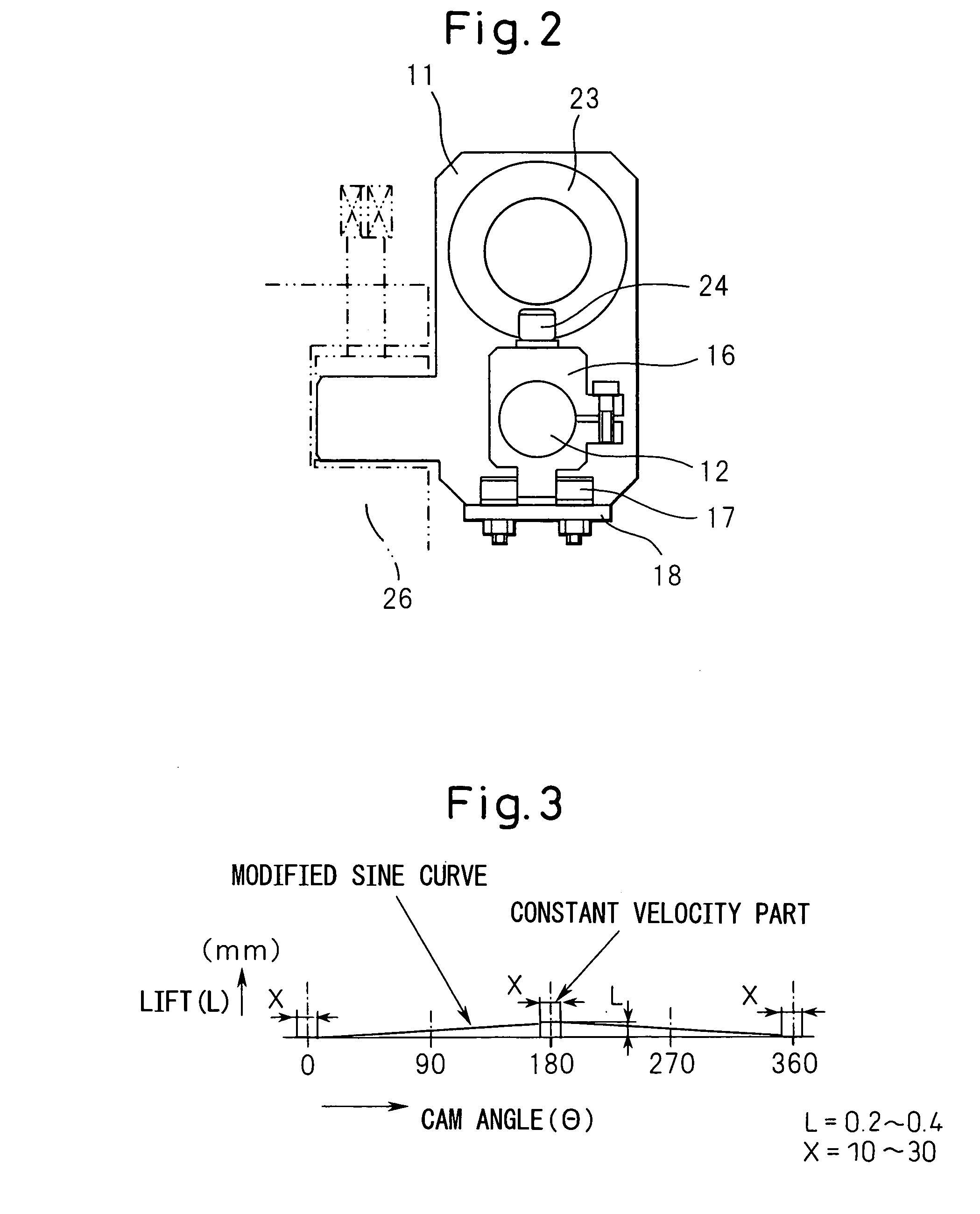
[0106] In order to improve the machining efficiency of small diameter and small angle tapered deep hole machining, the biting phenomenon of a taper-shaped cutting tool is focused on, and the biting is prevented by applying vibrations with low frequencies and great amplitudes to the cutting tool to reduce the load on the blade edge of the cutting tool and, at the same time, by using a modified sine curve as a vi...


PUM

PropertyMeasurementUnit
Angleaaaaaaaaaa
Angleaaaaaaaaaa
Angleaaaaaaaaaa

Abstract

A vibration machining device comprises a frame that forms a structure, a shaft that is rotatably held by the frame, an actuator that rotatably drives the shaft, a cam that is attached to the shaft and the cam surface of which reciprocates when the cam rotates because its height changes in the direction of rotation axis of the shaft, a spindle that holds a machining tool and which is supported so as to be able to reciprocate in its axial direction, and a transfer mechanism that transfers the reciprocation of the cam surface of the cam such that the spindle reciprocates in its axial direction. The reciprocating motion of the cam surface describes a modified sine curve during the period of one complete rotation of the cam.

Description

BACKGROUND OF THE INVENTION [0001] 1. Field of the Invention [0002] The present invention relates to a vibration machining device and a vibration machining method and, more particularly, to machining equipment and a machining method of a small diameter and small angle tapered deep hole, which is a tapered deep hole having a small diameter and a small angle, and is suitable to an application for machining a refrigerating cycle ejector. [0003] 2. Description of the Related Art [0004] Some ejector nozzles used in the refrigerating cycle have a small diameter and small angle tapered deep hole. Machining of such a small diameter and small angle tapered deep hole has brought about a problem that the blade edge of a taper-shaped tool may be broken in relation to a thrust force when the blade edge bites a machined workpiece, because the hole has a small taper angle. If the advancing speed of a tool is reduced in order to prevent the biting phenomenon, the machining efficiency is considerabl...

Claims


Application Information

Patent Timeline
IPC IPC(8): B23B47/28B23B47/34
CPCB23B29/125B23B41/06Y10T408/23Y10T408/03B23B47/34
Inventor MAKI, YUUZOUITOU, MASANORI
Owner DENSO CORP
Why Eureka
Try Eureka