
Guidewire system

a guidewire and system technology, applied in the field of intrabody guidewire systems, can solve the problems of adding undesirable complexity or thickness to the delivery system, no suggestion or reason for creating an exit, and a time-consuming process for exchange, so as to prevent the scratching of the enclosing blood vessel, and the effect of reducing the amount of distortion

Inactive Publication Date: 2006-05-11
EXISTENT
View PDF33 Cites 222 Cited by
  • Summary
  • Abstract
  • Description
  • Claims
  • Application Information

AI Technical Summary

Benefits of technology

[0022] An aspect of some embodiments of the invention relates to a stent in which a portion of the stent is crimped or bent out of the plane of the stent, for example prior to implantation. In an exemplary embodiment of the invention, the in plane and out of plane portions are interconnected by one or more torsion bars defined in the stent, for example, axial torsion bars. In an exemplary embodiment of the invention, the use of torsion bars allows a greater amount of distortion to be provided in the stent, without the distortion being irreversible by the deployment of the stent. In an exemplary embodiment of the invention, the torsion bars (and / or other modifications of the stent, for example annealing) are defined in locations that match a later expected crimping of the stent. Optionally, the stent includes a slot at one end, to assist in proper orientation in a crimping mechanism, for example which may include a matching nub. Alternatively or additionally, other alignment methods may be used, for example visual methods.
[0023] An aspect of some embodiments of the invention relates to a stent design for providing a channel in the stent. In an exemplary embodiment of the invention, the stent comprises a mesh like structure with multiple links on its surface. In one embodiment, only non-sequential links are selected to form the channel. Alternatively or additionally, links at the ends of the channel are bent, to guide the guidewire that passes through the channel and / or to prevent scratching of an enclosing blood vessel.

Problems solved by technology

As a catheter carrying a balloon and / or a stent are often difficult to navigate through the vascular system, and are also difficult to insert into a clogged location, common practice is to first guide a thin guidewire in conjunction with a guide-tube to the clogged location.
Nevertheless, since guidewires are long (˜2 meters) such exchange is a time consuming process.
However, there is no suggestion or reason for creating an exit at the balloon.
One complicated situation is that of a bifurcation stent implantation.
This may add undesirable complexity or thickness to the delivery system.

Method used


Image

  • Guidewire system
  • Guidewire system
  • Guidewire system

Examples


Embodiment Construction

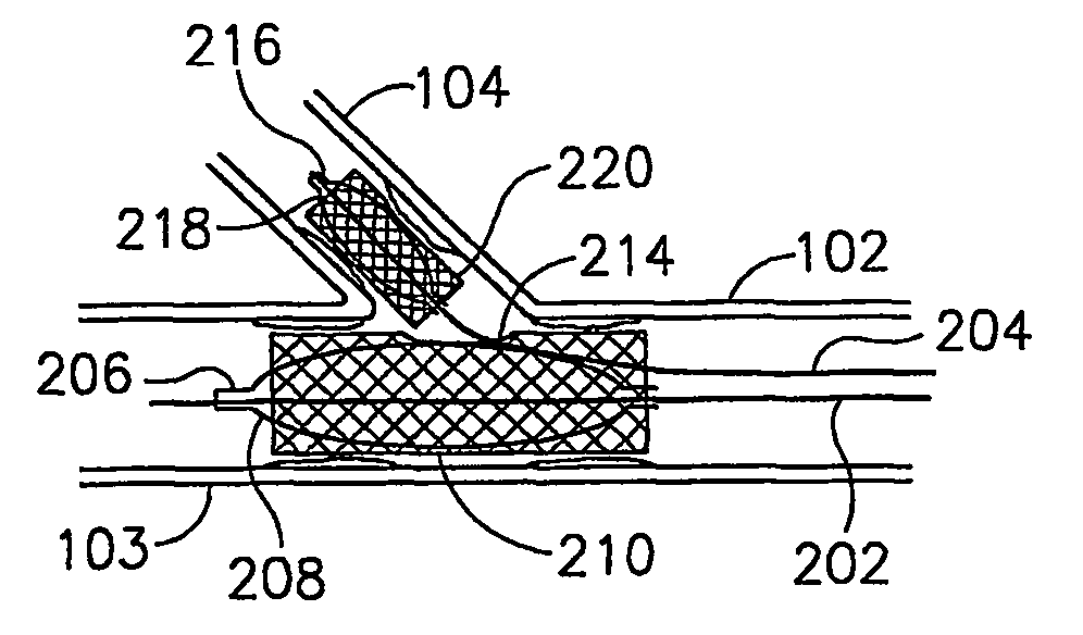
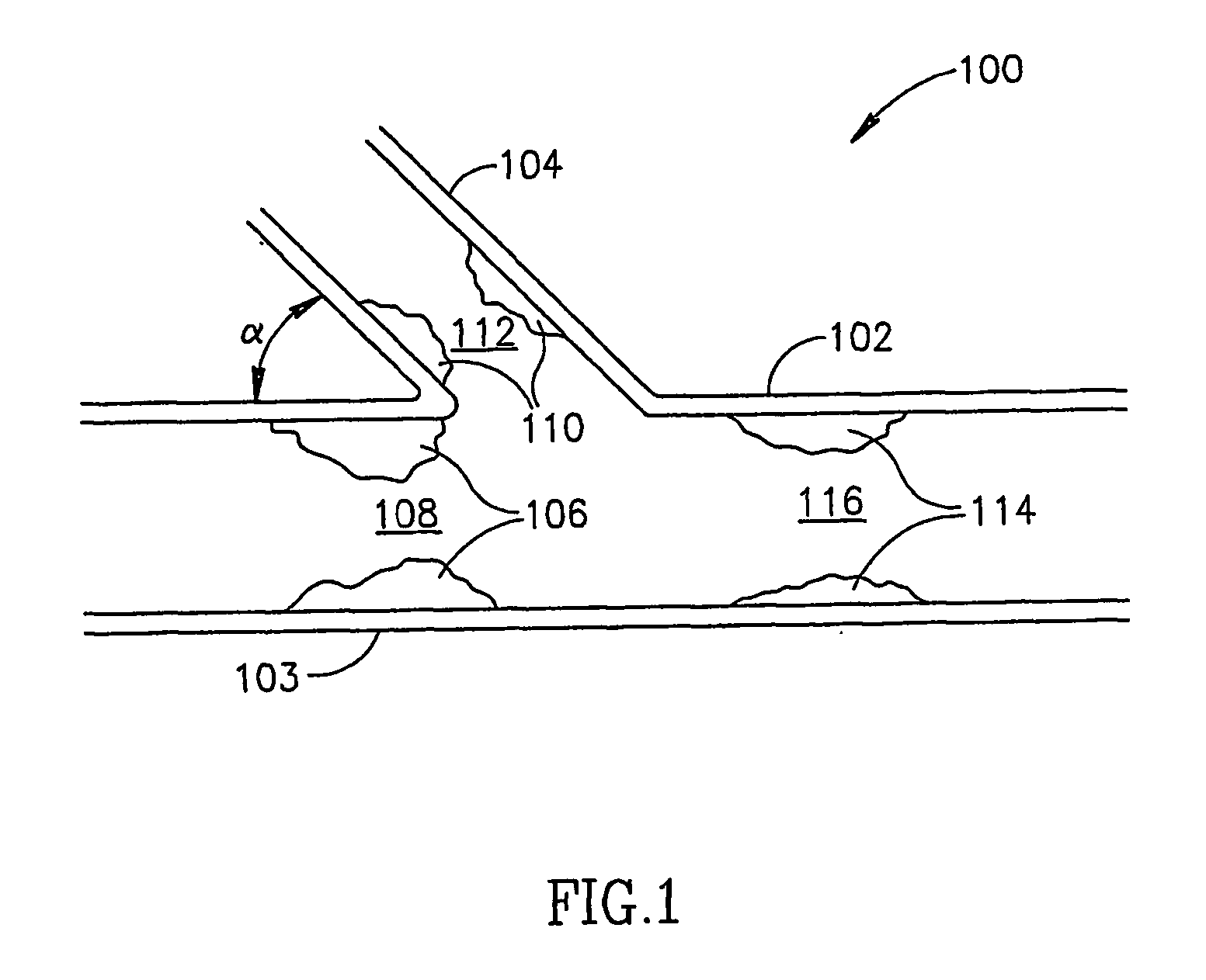
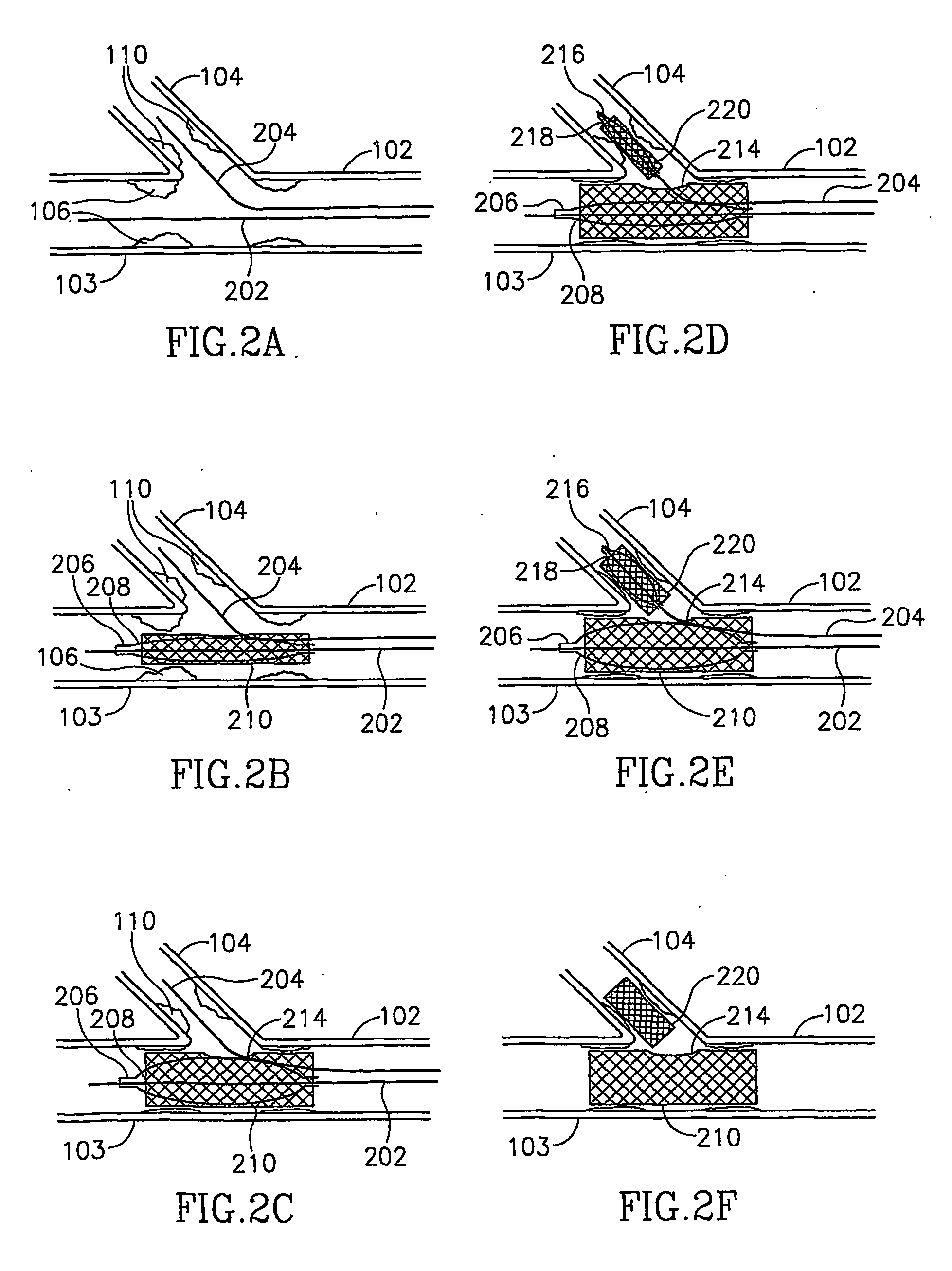
[0108]FIG. 1 shows a narrowed vessel bifurcation 100, which may be treated using methods and devices in accordance with exemplary embodiments of the invention. Typically, such a bifurcation comprises a main vessel 102, continuing as a main branch 103 with a branching-off side branch vessel 104, at an angle α. Vessels 102-104 may be, for example veins, arteries and / or grafts. In addition, in some cases, one or both branches are narrower than vessel 102. Different body portions and different people have different angles between the branches, for example, in the connection of cardiac arteries to the aorta, an angle α of 90° may exist.

[0109] Bifurcation 100 is shown narrowed at main branch 103, by plaque (or other narrowing source) 106, which creates a narrowed lumen 108. Alternatively or additionally, plaque 110 may create a narrowed lumen 112 in side branch 104 and / or plaque 114 may create a narrowing 116 in vessel 102.

[0110] Many stenosis amelioration tools exist for treating such ...


PUM


Abstract

A tool-carrying catheter, comprising: an elongate body adapted for insertion into a blood vessel; a tool section attached to a distal side of said body; and a guide-channel adapted to carry at least a guide-wire, wherein said catheter includes an entry port into said guide-channel for said guide wire and wherein said tool includes a distal exit for said guide wire from said guide-channel, defined in a side of said tool.

Description

RELATED APPLICATIONS [0001] The present application is a 119(e) of 60 / 387,929 filed Jun. 13, 2002, the disclosure of which is incorporated herein by reference.FIELD OF THE INVENTION [0002] The present invention relates to intrabody guidewire systems. BACKGROUND OF THE INVENTION [0003] Clogged arteries are often treated in a minimally invasive manner by the use of a balloon which is inflated at a clogged location and / or using a stent which maintains the patentcy of a clogged location. As a catheter carrying a balloon and / or a stent are often difficult to navigate through the vascular system, and are also difficult to insert into a clogged location, common practice is to first guide a thin guidewire in conjunction with a guide-tube to the clogged location. Often, several guidewires need to be tried until a suitable one is found. The guidewire maybe replaced by a thinner guidewire after the guide-tube reaches the clogged location. A catheter (e.g. a balloon catheter) is then provided o...

Claims


Application Information

Patent Timeline
IPC IPC(8): A61F2/06A61F2/84A61F2/90
CPCA61F2/856A61F2/91A61F2/915A61F2/954A61F2/958A61F2002/91508A61F2002/91516A61F2002/91525A61F2002/91541A61F2002/91558A61F2002/91575A61F2002/9522A61F2250/0048A61F2250/006A61M2025/1045A61F2230/0008A61F2230/001A61F2/9522A61F2/9524
Inventor GLOBERMAN, OREN
Owner EXISTENT
Learn More