Mobile bearing total elbow prosthesis, ulnar component, and associated kit
Inactive Publication Date: 2006-05-11
DEPUY PROD INC
17 Cites 31 Cited by
AI-Extracted Technical Summary
Problems solved by technology
The joints in the body are stressed or can be damaged in a variety of ways.
Over time, the normal use of a joint may wear down the cartilage and bring the moving bones in direct contact with each other.
In contrast, in normal use, a trauma to a joint, such as the delivery of a large force from an accident, for example an automobile accident, may cause considerable damage to the bones, the cartilage or to other connective tissue such as tendons or ligaments.
A surgeon may not always know prior to beginning an operation whether a patient would be better served by a semi-constrained or unconstrained elbow prosthesis.
Semi-constrained prosthesis are used in patients with inflammatory disease, which results in weaker soft tissues and bone erosion.
While current convertible prosthesis have been ...
View moreBenefits of technology
[0035] The technical advantage of the present invention also includes the ability to fit the stem shape to the canal and to fit the head shape to the condylar area. For example, according to another aspect of the present invention, either the ulnar or humeral component of the elbow prosthesis, or both, are modular or include two separatable pieces—one fitted into the canal and the other to the condylar area. Therefore, separate stems and articulating portions can be provided to have the prosthesis better fit the condylar area.
[0036] The technical advantages of the present invention further include the ability to lower manufacturing costs and to provide a less expensive tapered junction. For example, according to yet another aspect of the present invention, an elbow prosthesis is provided with a multi-piece humeral or ulnar component, which includes a tapered junction. One of the portions of the component has a conifrustrical-tapered component and the other has a conifrustrical cavity to receive the protrusion. Thus, the present invention provides for lower manufacturing cost by providing a less expensive junction, compared to multicomponent screw mechanisms or squared tapered junctions.
[0037] The technical advantages of the present invention further include the ability to convert the prosthesis from an unconstrained prosthesis to a semi-constrained prosthesis without removal of soft tissue or bone. For example, and according to another aspect of the present invention, an ulnar or a humeral component is provided with a first portion for implantation in a cavity and a second portion connected to the first portion positioned in the condylar area of the bone. The second portion may be connected to the first portion along the longitudinal axis of the component to permit the conversion of an unconstrained to a semi-constrained prosthesis without removing soft tissue or bone.
[0038] The technical advantages of...
View moreAbstract
An elbow prosthesis is provided. The elbow prosthesis includes an ulnar component. The ulnar component includes a first portion implantable in a cavity formed in the ulna and a second portion. The first portion of the ulnar component defines a longitudinal axis. The second portion of the ulnar component is rotatably connected to the first portion of the ulnar component about an axis normal to the longitudinal axis. The elbow prosthesis also includes a humeral component including a first portion implantable in a cavity formed in the humerus and a second portion. The second portion of the humeral component is operably connected to the second portion of the ulnar component.
Application Domain
Technology Topic
HumerusRight ulna +3
Image
Examples
- Experimental program(1)
Example
[0091] Embodiments of the present invention and the advantages thereof are best understood by referring to the following descriptions and drawings, wherein like numerals are used for like and corresponding parts of the drawings.
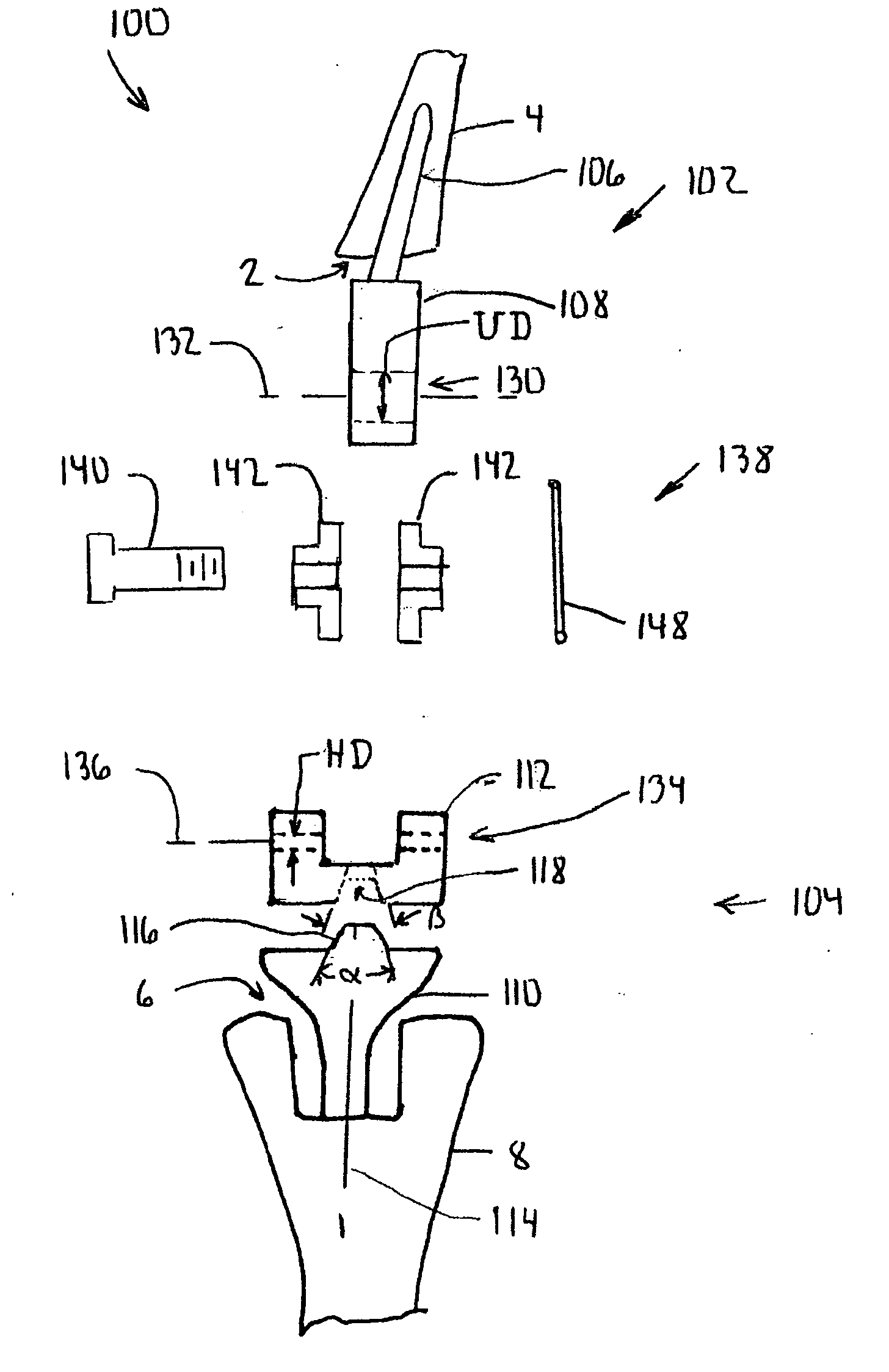
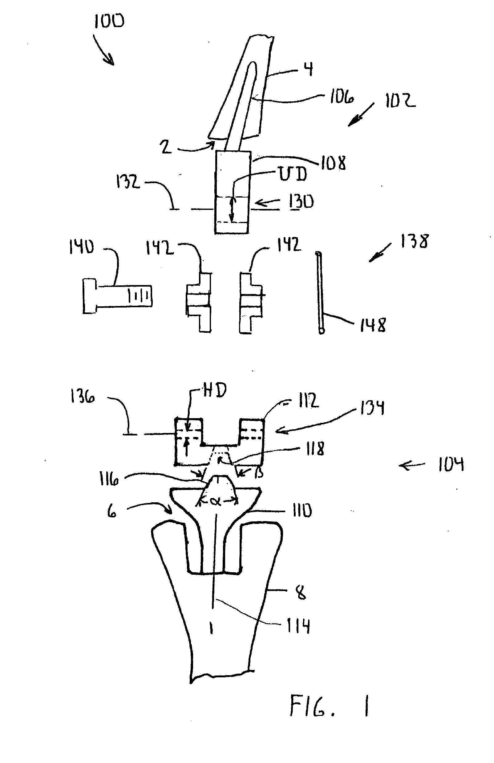
[0092] According to the present invention and referring now to FIG. 1, an embodiment of the present invention is shown as elbow prosthesis 100. The elbow prosthesis 100 includes an ulnar component 102 and a humeral component 104. The ulnar component 102 includes a first portion 106 of the ulnar component 102. The first portion 106 is implantable in a cavity 2 formed in the ulna 4. The ulnar component 102 also includes a second portion 108.
[0093] The humeral component 104 includes a first portion 110. The first portion 110 is implantable in a cavity 6 formed in the humerus 8. The humeral component 104 also includes a second portion 112 of the humeral component 104. The first portion 110 of the humeral component 104 defines a longitudinal axis 114 of the first portion 110. The second portion 112 of the humeral component is operably connected to the second portion 108 of the ulnar component 102. The second portion 112 of the humeral component 104 is rotatably connected to the first portion 110 of the humeral component 104 about the longitudinal axis 114.
[0094] The relative rotational motion of the second portion 112 of the humeral component 104 with respect to the first portion 110 of the humeral component 104 about the longitudinal axis 114 of the humeral component 104 provides for rotation about the long axis of the humerus.
[0095] The rotation of the second portion 112 with respect to the first portion 110 may be accomplished in any suitable manner. For example and is shown in FIG. 1, the first portion 110 may include an external protrusion 116 positioned about longitudinal axis 114 of the humeral component 104. The external protrusion 116 cooperates with a cavity 118 formed in the second portion 112. It should be appreciated that the cavity 116 and the protrusion 118 may be reversed with the protrusion being located in the second portion and the cavity in the first portion.
[0096] As shown in FIG. 1, the external protrusion may be tapered or have a conofrustical shape. The cavity 118 may likewise have a conifrustical shape for receiving the protrusion 116. In order that the second protrusion 112 may rotate with respect to the first portion 110, preferably, the protrusion 116 of the cavity 118 is adapted to provide for relative motion between each other. (Such relative motion may be accomplished in many ways, for example, by providing the taper angle to be large enough not to provide self-locking.) For example, the included angle α of the first portion 110 may be, for example, a large enough angle i.e. 5°-30° and the included angle β of the cavity 118 of the second portion 112 may likewise have an angle β of 5°-30° so that the second portion 112 does not lock with the first portion 110.
[0097] Alternatively, the included angle of the taper in the protrusion 116 and the angle in the cavity 118 may be different to prevent locking of the second portion 112 to the first portion 110.
[0098] Alternatively, other designs may be provided to avoid the locking of the second portion to the first portion. For example, and as is shown in FIG. 1A, a humeral component 104A may include a first portion 110A including a protrusion 116A defining an included angle αA. The protrusion 116A mates with cavity 118A formed on second portion 112A. The cavity 118A has an included angle αB. The angles αA and βA are the same.
[0099] The first portion 110A of the humeral component 104A includes a first portion face 120A for contact with second portion face 122A of the second portion 112A of the humeral component 104A. The first portion face 120A and the second portion face 122A are adapted to provide for the protrusion 116A to be spaced from the walls of the cavity 118A to provide for motion rotationally of the second portion 112A with respect to the first portion 110A.
[0100] Referring now to FIG. 1B, yet another embodiment for providing for first and second portion that may have relative motion between each other is in the form of a humeral component 104B. The humeral component 104B includes a first portion 110B defining a protrusion 116B. The humeral component 104B further includes a second portion 112B defining a cavity 118B. The protrusion 116B and the cavity 118B are provided with different included angles in the respective tapered features. For example, and as is shown in FIG. 1B, the protrusion 116B includes an included angle αB which is smaller than the included angle βB of the cavity 118B. The protrusion 116B contacts the cavity 118B at tip 124B of the protrusion 116B. Thus, the second portion 112 may be rotatable with respect to the first portion 10B.
[0101] Referring now to FIG. 1C, yet another embodiment of the present invention to provide for rotation of the second portion with respect to the first portion is shown as humeral component 104C. The humeral component 104C includes a first component 110C defining a protrusion 116C having an included angle αC. The humeral component 104C includes a second component 112C that defines a cavity 118C for cooperation with the protrusion 116C. The cavity 118C defines an included angle βC. The angle βC is greater than the angle αC so that the protrusion 116C contacts the cavity 118C at base 126C of the protrusion 116C. Thus the second portion 112C may rotate with respect to the first portion to 110C.
[0102] Referring now to FIG. 1D, yet another embodiment of the present invention is shown as humeral component 104D. The humeral component 104D includes a first portion 110D which is rotatably connected to second portion 112D. The second portion 112D is connected to first portion 110D by means of a cylindrical connection. The first portion 110D includes a cylindrical protrusion 116D which mates with a cylindrical opening 118D formed in the second portion 112D. It should be appreciated that the cylindrical opening 118D may be made for rotatably fitting to cylindrical protrusion 116D. Preferably, the cylindrical opening 118D may be normal to slightly larger than the cylindrical protrusion 116D.
[0103] To constrain the second portion 112D in close proximity to the first portion 110D as shown FIG. 1D, the cylindrical protrusion 116D may include a cylindrical rim 125D, which cooperates with groove 128D formed in the second portion 112D of the humeral component 104D. The groove 128D and the rim 125D serve to secure the second portion 112D to the first portion 110D.
[0104] Referring again to FIG. 1, the ulnar component 102 is operabley connected to the humeral component 104. As shown in FIG. 1, the elbow prosthesis 100 is a semi-constrained prosthesis. The ulnar component 102 is therefore rotatably connected to the humeral component 104. It should be appreciated that the elbow prosthesis 100 may likewise be designed for use as an unconstrained prosthesis.
[0105] While the ulnar component 102 may be operably connected to the humeral component 104 in any suitable manner, for example, and is shown in FIG. 1, the second portion 108 of the ulnar component 104 defines an ulnar opening 130 defining ulnar rotating axis 132. Similarly, the second portion 112 of the humeral component 104 includes a humeral opening 134 defining a humeral rotating axis 136.
[0106] A connecting apparatus 138 may be utilized to connect rotatably the ulnar component 102 to the humeral component 104. The connector 138 may have any suitable shape and may as is shown in FIG. 1, include a pin 140. The pin 140 may be directly matingly fitted to 130 and 134 or as shown in FIG. 1, the prosthesis 100 may include a pair of spaced apart bushings 142 which are positioned between the ulnar and humeral components 102 and 104 and fitted to openings 130 and 134.
[0107] The components of the elbows prosthesis 100 may be made of any suitable, durable material that is compatible to the human body. For example, the components of the elbow prosthesis 100 may be made of a metal, plastic, or a composite material. If made of a metal, the components of the elbow prosthesis may be made of, for example, cobalt chromium alloy, a stainless steel alloy, or a titanium alloy, if made of a plastic the components of the elbow prosthesis 100 may be made of, for example, polyethylene. If made of polyethylene, the components of the elbow prosthesis 100 may be made of an ultra-high molecular weight polyethylene.
[0108] The ulnar component 102 including the first portion 106 and the second portion 108 as well as the humeral component 104 including the first portion 110 and the second portion 112 may be made of a metal. The pin 140 may likewise be made of a metal. The bushings 142 may be made of a plastic or a metal.
[0109] As shown in FIG. 1, the ulnar component 102 may be integral or, in other words, the first portion 106 and the second portion 108 may be integral to each other.
[0110] Alternatively, according to another embodiment of the present invention and referring now to FIG. 1E, the ulnar component may be in the form of an ulnar component 102E, which is modular. For example, the ulnar component 102E may include a first portion 106E, which is cooperable with the cavity 2 of the ulna 4. The ulnar component 102E may further include a second portion 108E, which is separate from first portion 106E. For example, the first portion 106E may include a protrusion 144E, which cooperates with a cavity 146E formed in the second portion 108E. The protrusion 144E and cavity 146E may be conifrustical or cylindrical or have any suitable shape.
[0111] Referring now to FIG. 2, the humeral component 104 of the elbow prosthesis 100 is shown in greater detail. The humeral component 104 includes the first or stem portion 110 which is fitted into the cavity 6 of the humerus 8 as well as the second or articulating portion 112. The articulating portion 112 is connected to the stem portion 110 by means of, for example, the protrusion 116 which extends from the stem portion 110 and which cooperates with the cavity 118 in the articulating portion 112. The articulation portion 112 is permitted to rotate about longitudinal axis 114 of the stem portion 110. The opening 134 is formed in the articulating portion 112 and defines pivoting elbow axis 136.
[0112] Referring now to FIG. 3, the elbow prosthesis 100 is shown implanted in the humerus 8 and ulna 4. The elbow prosthesis 100 includes the humeral component 104 which is positioned in the humerus 8 as well as the ulna component 102 which is positioned in the ulna 4.
[0113] Referring now to FIG. 4, the humeral component 104 of the elbow prosthesis 100 is shown in greater detail. The humeral component 104 includes a stem portion 110 including a conifrustical protrusion 116 extending from an end of the stem portion 110.
[0114] Referring now to FIG. 5, the articulating portion 112 of humeral component 104 of the elbow prosthesis 100 is shown in greater detail. The articulation portion 112 includes the cavity 118 for receiving the protrusion 116 of the stem portion 110 as well as a pair of humeral openings 134 which define rotation axis 136.
[0115] Referring now to FIG. 6, the humeral component 104 is shown in a perspective exploded view. The humeral component includes the stem portion 110 which includes the protrusion 116 which cooperates with cavity 118 formed in articulating portion 112 of the humeral component 104. The articulating portion 112 includes the openings 134 defining pivoting center 136.
[0116] Referring now to FIG. 7, the connector 138 for use with the humeral component 104 and ulnar component 102 to form the elbow prosthesis 100 is shown in greater detail. The connector 138 includes the pin 140 which cooperates with bushings 142 and wire 148 to form the connector 138. The pin 140 includes a body 150 from which head 152 extends. The body 150 defines a cross hole 154 for receiving the wire 148. The body 150 of the pin 140 opening defines pin diameter PD which matingly fits with ulnar diameter UD and with bushing opening UBD. The bushings 142 defined bushing hub diameter HBD which matingly fits with humeral opening diameter HD shown in FIG. 8. Cross-hole 154 of the pin 140 defines a diameter CHD which mates with diameter WD of the wire 148.
[0117] Referring now to FIG. 8, the connector 138 is shown in position with the ulnar component 102 and the humeral component 104. The bushings 142 are positioned in humeral opening 134 with each of the bushings 142 having the diameter HBD fitting into diameter HD of the humeral openings 134. The pin 140 is fitted into ulnar opening 130 with the ulnar opening diameter UD being sized for mating fit with body diameter PD of the body 150 of the pin 140. The connector 138 thus matingly interlocks the second portion 112 of the humeral component 104 with the second portion 108 of the ulnar component 102 to form the semi-unconstrained elbow prosthesis 101.
[0118] Referring now to FIGS. 9, 10 and 10A, another embodiment of the present invention is shown as elbow prosthesis 200. Elbow prosthesis 200 includes a semi-constrained elbow prosthesis 201 as is shown in FIGS. 9 and 10 and an unconstrained elbow prosthesis 203 as is shown in FIG. 10A.
[0119] Referring now to FIG. 9, the semi-constrained elbow prosthesis 201 includes an ulnar component 202, a humeral component 204, and a connector 238 for operatively connecting the ulnar component 202 to the humeral component 204.
[0120] The ulnar component 202 includes a stem portion 206 which is fitted into cavity 2 of the ulna 4. An articulating portion 208 extends from the stem portion 206 to form the ulna component 202. The articulating portion 208 defines a transverse opening 230.
[0121] The humeral component 204 includes a stem portion 210 which is fitted into cavity 6 of the humerus 8. The humeral component 204 is different than the humeral component 104 of the prosthesis 100 of FIGS. 1-7 in that the humeral component 204 further includes a bearing 256. The bearing 256 serves to assist in providing for a mobile bearing or a rotatable humeral component 204. The bearing 256 includes a protrusion 258 which is fitted into cavity 218 formed in the stem portion 210.
[0122] The bearing 256 is positioned between the stem portion 210 and articulating portion 212 of the humeral component 204. The bearing 256 further defines a bearing cavity 260 which mates with protrusion 216 extending from articulating portion 212 of the humeral component 204. The articulating portion 212 defines transverse opening 234 for receiving the connector 238.
[0123] The connector 238 includes a pin 240 which cooperates with bushings 242 and wire 248 to form the connector 238. The pin 240 fits through opening 230 of the ulnar component 202 and through the opening 234 of the articulating portion 212 of the humeral component 204 to form the semi-constrained elbow prosthesis 201.
[0124] Referring now to FIG. 10, the humeral component 204 of the semi-constrained elbow prosthesis 201 is shown in greater detail. The humeral component 204 includes the stem component 210, the bearing 256, and the articulating component 212. In order to provide the rotation in the direction of arrow 262 between the articulating component 212 and the stem component 210, the bearing 256 is permitted to rotate with at least one of the stem component 210 and the articulating component 212. For example, the cavity 218 formed in the stem component 210 may be rotatably fitted with the bearing protrusion 258. Alternatively, the bearing protrusion 258 and the cavity 218 may define a rigid connection.
[0125] Alternatively or in addition, the bearing cavity 260 of the bearing 256 may be rotatably fitted to the protrusion 216 of the articulating component 212 to permit the bearing 256 to rotate with respect to the stem component 210. It should be appreciated that alternatively the protrusion 216 and the bearing cavity 260 may represent a rigid connection.
[0126] Referring now to FIG. 10A, an unconstrained prosthesis 203 of the prosthesis 200 is shown. The unconstrained prosthesis 203 includes an ulnar component 264 which is in unconstrained cooperation with humeral component 266. The ulnar component 264 is similar to the ulnar component 202 of FIGS. 10 and 11 except that the ulnar component 264 includes an articulating portion 270 which is different than the articulation portion 208 of the ulnar component 202.
[0127] The ulnar component 264 includes a stem component 268 which is similar to the stem portion 206 of the ulnar component 202 of FIGS. 10 and 11. The articulation portion 270 of the ulnar component 264 includes an articulating surface 272 which mates with articulating surface 278 of articulation portion 274 of the humeral component 266. The humeral component 266 includes stem portion 210 which is connected to bearing 256.
[0128] The articulating portion 274 of the humeral component 266 includes a protrusion 276 which cooperates with bearing cavity 260 of the bearing 256. The articulating surface 272 of the ulnar component 264 cooperates with the articulating surface 278 of the humeral component 266 to provide the unconstrained prosthesis 203.
[0129] Referring now to FIG. 11, yet another embodiment of the present invention, is shown as elbow prosthesis 300. The elbow prosthesis 300 includes an ulnar component 302. The ulnar component 302 includes a first portion 306 of the ulnar component 302 which is implantable in cavity 2 formed in the ulna 4. The ulnar component 302 further includes a second portion 308 of the ulnar component 302. The first portion 306 of the ulnar component 302 defines a longitudinal axis 380 of the first portion 306. The second portion 308 of the ulnar component 302 is designed to be rotatable connected to the first portion 306 of the ulnar component 302 about an axis 382 which is normal or perpendicular to the longitudinal axis 380.
[0130] The elbow prosthesis 300 further includes a humeral component 304. The humeral component 304 includes a first portion 310 of the humeral component 304. The first portion 310 is implantable in a cavity 6 formed in the humerus 8. The humeral component 304 further includes a second portion 312. The second portion 312 of the humeral component 304 is operably connected to the second portion 308 of the ulnar component 302.
[0131] The humeral component 304 may be connected to ulnar component 302 in any suitable manner. For example, a connector 334 may be used and fitted to an ulnar opening 130 and to a humeral opening 336 to provide for a pivoting connection of the humeral component 304 to the ulnar component 302.
[0132] Referring now to FIGS. 12-21, yet another embodiment of the present invention is shown as semi-constrained elbow prosthesis 401 of elbow prosthesis 400. The elbow prosthesis 400 includes an ulnar component 402. The ulnar component 402 includes a first portion or stem 406 which is implantable in a cavity 2 formed in the ulna 4. The ulnar component 402 also includes a second or articulating portion 408. The first portion 406 of the ulnar component 402 defines a longitudinal axis 480 of the ulnar stem portion 406. The ulnar articulating portion 408 of the ulnar component 402 is rotatably connected to the ulnar stem portion 406 of the ulnar component 402 about an axis 482 which is normal to the longitudinal axis 480.
[0133] The semi-constrained elbow prosthesis 401 also includes a humeral component 404. The humeral component 404 includes a first portion or stem portion 410 which is implantable in a cavity 6 of the humerus 8. The humeral component 404 also includes a second portion or articulating portion 412. The articulating portion of the humeral component 404 is operably connected to second or articulating portion 408 of the ulnar component 402.
[0134] The ulnar component 402 may be operably connected to humeral component 404 in any suitable fashion. For example, and is shown in FIG. 12, the elbow prosthesis 401 is a semi-constrained prosthesis. In the semi-constrained prosthesis 401 the ulnar component 402 is pivotally connected to the humeral component 404.
[0135] For example, and is shown in FIG. 12, the semi-constrained elbow prosthesis 401 further includes a connector 438 for pivotally connecting the ulnar component 402 to the humeral component 404. The connector 438, may as shown in FIG. 12, include a pin 440 and a pair of spaced apart bushings 442 which cooperate with a wire 448 as well as with an opening 430 formed in the articulating portion 408 of the ulnar component 402 and with opening 434 formed in the articulating component 412 of the humeral component 404 to provide the pivoting motion of the semi-constrained elbow prosthesis 401.
[0136] Referring now to FIGS. 13 and 14, the humeral component 404 is shown in greater detail. The humeral component 404 includes the stem portion 410 which is fitted into cavity 6 of the humerus 8 as well as an articulating portion 412 which extends from the stem portion 410 of the humeral component 404. As shown in FIGS. 13 and 14, the stem portion 410 and the articulating portion of the humeral component 404 are integral with each other. It should be appreciated that the stem portion 410 and the articulating portion 412 may be separate components.
[0137] The articulating portion 412 of the humeral component 404 defines a pair of spaced apart transverse openings 434 for receiving the connector 438 of FIG. 12.
[0138] Referring now to FIGS. 15, 16, and 17 the ulnar stem portion 406 of the ulnar component 402 is shown in greater detail. The ulnar stem component 406 includes a stem 484 which defines the longitudinal axis 480 of the ulnar stem component 406. Extending from the stem 484 is the ulnar stem component body 486. The ulnar stem component body 486 defines a support face 488 from which plug 490 extends. The body 486 further defines a lip 492 which extends from transverse member 494 of the body 486. The plug 490 and the lip 492 serve to contain the ulnar-articulating component 408 to rotate about transverse axis 482 of the ulnar stem portion 406 in the direction of arrows 496.
[0139] Referring now to FIGS. 18, 19 and 20, the ulnar articulating portion 408 of the ulnar component 402 of the semi-constrained prosthesis 401 is shown in greater detail. The ulnar articulating portion 408 includes a support surface 497 for cooperation with support surface 488 of the ulnar stem portion 406. A pivot hole 498 is formed in articulation portion support surface 497. The pivot hole 498 is adapted to receive the plug 490 of FIG. 16 for rotation therewith. The ulnar articulating portion 408 further defines a groove 499 adapted to mate with the lip 492 of the ulna stem portion 406.
[0140] Referring now to FIG. 21, the semi-constrained ulnar component 402 is shown in greater detail. The ulnar component 402 of semi-constrained elbow prosthesis 401 includes the stem portion 406 to which the articulating portion 408 is pivotally connected.
[0141] Pivot hole 498 in the support surface 497 of the ulnar articulating component 408 receives plug 490 of the stem portion 406 constraining the articulating portion 408 in a pivoting position about axis 482. Lip 492 of the stem portion 406 engages with groove 499 formed in the articulating portion 408 to constrain articulating portion 408 with respect to the stem portion 406.
[0142] Referring again to FIG. 15, the articulating portion 408 is shown in phantom being assembled unto the ulnar stem component 406 to form the ulnar component 402. The ulnar articulating portion 408 is shown in phantom in first position 481 in a position generally normal or perpendicular to the longitudinal axis 480 of the ulnar stem component 406. From the first position 481, the ulnar articulating portion 408 may be advanced in the direction of arrow 483 until the support surface 497 of the ulnar articulating portion 408 rests against support surface 488 of the ulnar stem portion 406. The ulnar-articulating portion 408 is then rotated from first position 481 to second position 485 to provide for the ulnar component 402.
[0143] Referring now to FIG. 12A, unconstrained elbow prosthesis 403 of the elbow prosthesis 400 is shown. The unconstrained elbow prosthesis 403 includes an ulnar unconstrained assembly 464 which mates in an unconstrained fashion with humeral component 466. The humeral component 466 is similar to the humeral component 406 of FIGS. 12-21 except that the humeral component 466 includes an articulating surface 478 for unconstrained cooperation with articulating surface 472 of the ulnar unconstrained assembly 464.
[0144] The ulnar-unconstrained assembly 464 includes the ulnar stem portion 406 which mates with ulnar unconstrained portion 470. The ulnar unconstrained portion 470 is similar to the ulnar semi-constrained articulating portion 408 of the ulnar component 402 of the FIGS. 12-21 except the ulnar unconstrained articulating portion 470 includes an articulating surface 472 for cooperation with the articulating surface 478 of the humeral component 466.
[0145] Referring now to FIG. 21A, yet another embodiment of the present invention is shown as semi-constrained elbow prosthesis 401A. The elbow prosthesis 401A is similar to the elbow prosthesis 401 of FIGS. 12-21 except that the ulnar prosthesis 401A includes ulnar component 402A which is somewhat different than the ulnar component 402 of FIGS. 12-21.
[0146] For example, and is shown in FIG. 21A, the ulnar component 402A includes a stem portion 406A and an articulating portion 408A. Stem portion 406A of the ulnar component 402A includes stops 489A which are positioned on the stem portion 406A to limit the rotation of the articulating portion 408A about the first axis 482A.
[0147] In fact, and is shown in FIG. 21A, the stops 489A cooperate with faces 487A of the ulnar articulating component 408A to limit the rotation of the articulating portion 408A with respect to the stem portion 406A for example, to a pivoting angle α. α may, for example, be from 10 to 60°.
[0148] According to the present invention and referring now to FIG. 22, yet another embodiment of the present invention is shown as elbow prosthesis 500. The elbow prosthesis 500 is shown in FIG. 22 in the form of a semi-constrained elbow prosthesis 501. The semi-constrained elbow prosthesis 501 includes an ulnar component 502 which mates with a humeral component (not shown) similar to humeral component 404 of FIGS. 12-21. The semi-constrained elbow prosthesis 501 further includes a connector (not shown) similar to the connector 438 of the elbow prosthesis 400 of FIGS. 12-21.
[0149] The ulnar component 502 includes a stem portion 506 as well as an articulating portion 508. The stem portion 506 is similar to the stem portion 406 of the elbow prosthesis 400 of FIGS. 12-21 but includes a plug 590 which is somewhat different than the plug 490 of the stem portion 406 of the elbow prosthesis 400 of FIGS. 12-21. The plug 590 further includes a rim 592 extending from the plug 590. The stem portion 506 unlike the stem portion 406 of the elbow prosthesis 400 of FIGS. 12-21 does not include a lip.
[0150] The articulating portion 508 of the ulnar component 502 of the semi-constrained elbow prosthesis 501 of FIG. 22, is somewhat similar to the articulating portion 408 of the elbow prosthesis 400 of FIGS. 12-21 except that the articulating portion 508 includes a pivot hole 598 which further defines a recess 599 for cooperation with the rim 592 of the plug 590 of the stem portion 506 of the ulnar component 502. The articulating portion 508 defines an ulnar opening 530 for receiving the connector (not shown) which cooperates with the ulnar component (not shown) to form the semi-constrained elbow prosthesis 501.
[0151] Referring now to FIGS. 23-30, yet another embodiment of the present invention is shown as elbow prosthesis 600. Elbow prosthesis 600 is similar to the elbow prosthesis 100 of FIGS. 1-8 except that the elbow prosthesis 600 uses a different rotation mechanism for the humeral component in that the elbow prosthesis 600 uses a lip/groove or dovetail connection.
[0152] Referring now to FIG. 23, the semi-constrained elbow prosthesis 601 of the elbow prosthesis 600 is shown. The semi-constrained elbow prosthesis 601 includes an ulnar component 602 which is operably connected to a humeral component 604. The ulnar component 602 includes a stem portion 606 from which an articulating portion 608 extends. The articulating portion 608 defines a transverse opening 630 therein.
[0153] The humeral component 604 includes a humeral stem portion 610 from which a humeral semi-constrained articulating portion 612 extends. The humeral semi-constrained articulating portion 612 defines a transverse opening 634 therethrough.
[0154] A connector 638 as shown in FIG. 23 includes a pin 640 which is slidably receivable in a pair of spaced apart bushings 642. The connector 638 further includes a wire 648 which is secured to the pin 640.
[0155] Referring now to FIGS. 24 and 25, the stem portion 610 of the humeral component 604 of the semi-constrained elbow prosthesis 601 is shown in greater detail. The humeral stem 610 includes a distal stem 611 from which a body 613 extends. The body 613 defines a cavity 615 opposed to the stem 611. The cavity 615 is formed from lips 617 formed in the body 613. A central hole 619 is formed in the cavity 615. The stem 611 defines a longitudinal axis 614 which, as shown in FIGS. 24 and 25, defines the center of the central hole 619 and the center of the opposed lips 617. The body 613 of the humeral stem portion 610 defines a support surface 621.
[0156] Referring now to FIG. 26, articulating portion 612 of the humeral component 604 of the semi-constrained elbow prosthesis 601 is shown in greater detail. The humeral articulating portion 612 may be integral or may as shown in FIG. 26 be made of more than one component. For example, the humeral articulating portion 612 may include a base 623 and a body 625 which extends from the base 623.
[0157] The base 623 and the body 625 may be made of any suitable, durable material. For example, the base 623 and body 625 may be made of a metal or plastic. The base 623 may be made of a plastic and the body 625 may be made of metal. The base 623, if made of a plastic, may provide for the mobile bearing or rotation capability.
[0158] The base 623 may include a pair of spaced apart pegs 627 which mate with cavities 629 formed in the body 625. The base 623 of the humeral articulating portion 612 may define an end face 631 from which dovetail 633 centrally extends. The dovetail 633 defines a support surface 635 as well as a central pivot 637. The body 625 may define a pair of spaced apart transverses openings 634 for cooperation with the bushings 642 of FIG. 23. The dovetail 633 defines opposed recesses 639 for cooperation with the lips or protrusions 617 formed in the humeral stem portion 610 of FIG. 24.
[0159] Referring now to FIG. 26A, the humeral articulating portion 612 may be assembled unto the humeral stem portion 610 of the humeral component 604 in any suitable manner. For example, and is shown in FIG. 26A, the humeral articulating portion 612 may be positioned in first position 641 as shown in solid over the humeral stem portion 610. The humeral articulating portion 612 may be advanced in the direction of arrow 645 until the support surface 635 of the dovetail 633 of the articulating portion 612 rests against the support surface 621 of the humeral stem portion 610 (see FIGS. 25 and 26). The pivot 637 of the articulating portion 612 may be fitted into central hole 619 of the humeral stem portion 610. When the surfaces 621 and 635 are in contact, the humeral articulating portion 612 may be rotated in the direction of arrow 645 from first position 641 to second position 647, as shown in phantom, thereby securing the humeral articulating portion 612 to the humeral stem portion 610 to form the humeral component 604.
[0160] Referring now to FIG. 27, the humeral component 602 of the semi-constrained elbow prosthesis 601 is shown in greater detail. The ulnar component 602 includes a stem portion 606 from which articulating portion 608 extends. The articulating portions 608 define the transverse opening 630 for receiving the connector 638.
[0161] Referring now to FIG. 28, unconstrained elbow prosthesis 603 of the elbow prosthesis 600 is shown. The unconstrained elbow prosthesis 603 includes an ulnar unconstrained component 664 which cooperates in an unconstrained fashion with unconstrained humeral component 666 to form the unconstrained elbow prosthesis 603.
[0162] The unconstrained ulnar component 664 includes an ulnar stem portion 668 which is fitted into the cavity 2 of the ulna 4. An ulnar articulating portion 670 extends from the ulnar stem portion 668. The ulnar articulating portion 670 defines ulnar articulating surface 672.
[0163] The humeral unconstrained component 666 includes a humeral stem portion 610 which is fitted into cavity 6 of the humerus 8. Unconstrained articulating portion 674 extends from the humeral stem portion 610. The unconstrained articulating portion 674 defines humerus articulating surface 678 which mates with ulnar articulating surface 672 of the unconstrained ulnar component 664 to form the unconstrained elbow prosthesis 603.
[0164] Referring now to FIG. 29, the articulating portion 674 of the humeral component 666 is shown in greater detail. The articulating portion 674 may include a base 671 which is connected to the body 673 to form the unconstrained articulating portion 674. The base 671 and the body 673 may be integral or may, as shown in FIG. 29, be compromised of different components. For example, and as shown in FIG. 29, the base 671 may include a pair of spaced apart pegs 667 for securing the body 671 to the base 673.
[0165] The base 671 and the body 673 may be made of any suitable, durable material. For example, the body 673 may be made of a metal and the base 671 may be made of a plastic to provide for a bearing surface for the pivotal connection of the humeral component 666.
[0166] The base 671 may include a dovetail 675 centrally positioned and extending from end 687 of the base 671. The dovetail 675 may define a support surface 677 from which a central cylindrical pivot 679 may extend. The dovetail 675 of the humeral unconstrained articulating portion 674 may be similar to the dovetail 633 of the humeral semi-constrained articulating portion 612 so that the humeral articulating portions 612 and 674 may be interchanged.
[0167] Referring now to FIG. 30, unconstrained ulnar component 664 of the unconstrained elbow prosthesis 603 is shown in greater detail. The unconstrained ulnar component 664 includes a stem portion 668 from which an articulating portion 670 extends. The articulating portion 670 includes articulating surface 672 for cooperation with the articulating surface 678 of the humeral unconstrained component 666.
[0168] Referring now to FIG. 30A, yet another embodiment of the present invention is shown as unconstrained elbow prosthesis 603A. The unconstrained elbow prosthesis 603A is similar to the elbow prosthesis 603 of FIGS. 28-30 except that the unconstrained elbow prosthesis 603A includes an ulnar component 664A which is different than the unconstrained ulnar component 664 of the unconstrained elbow prosthesis 603 of FIGS. 28-30. For example, and is shown in FIG. 30A, the ulnar component 664A may be used for both an unconstrained and semi-constrained prosthesis.
[0169] As shown in FIG. 30A, the ulnar component 664A includes a stem portion 668A from which an articulating portion 670A extends. The articulating portion 670A includes both an ulnar articulating surface 672A for use in an unconstrained prosthesis as well as a transverse opening 630A for use in a semi-constrained elbow prosthesis.
[0170] Referring now to FIG. 31, yet another embodiment of the present invention is shown as elbow prosthesis 700. The elbow prosthesis 700 of FIG. 31 may be used for both rotation about peg shift version as well as for rotation about peg shift carrying angle. The elbow prosthesis 700 of FIG. 31 thus provides both for a mobile bearing configuration on the humeral side of the elbow prosthesis as well as for a mobile bearing prosthesis on the ulnar side of the elbow prosthesis.
[0171] Continuing to refer to FIG. 31 semi-constrained elbow prosthesis 701 of the elbow prosthesis 700 is shown. It should be appreciated that the elbow prosthesis 700 of FIG. 31 may be used in an unconstrained version similar to the versions of other embodiments of the present invention in addition to the semi-constrained prosthesis 701 in FIG. 31.
[0172] The semi-constrained elbow prosthesis 701 includes an ulnar component 702 which is connected to a humeral component 704 by a connector 738.
[0173] The ulnar component 702 includes an ulnar stem portion 706 which includes a part 788 which is fitted into cavity 2 of ulna 4. The ulnar component 702 further includes an ulnar articulating portion 708 which is operably connected to the ulnar stem component 706. The ulnar articulating component 708 is connected to the ulnar stem component by means of a pivot hole 798 extending from the ulnar articulating portion 708, which cooperates with plug 790 formed in the ulnar stem portion 706. A lip 792 formed on the ulna stem portion cooperates with a groove 799 formed in ulna articulating portion 708. The ulna articulating portion 708 defines opening 730 for receiving connector 738.
[0174] The humeral component 704 includes a stem portion 710 which is fitted into cavity 6 of the humerus 8. The humeral component 704 includes an articulating portion 712 which is rotatably connected to the stem portion 710. The articulating portion 712 defines a transverse opening 734 for receiving the connector 738.
[0175] The connector 738 may, as shown in FIG. 31 include a pin 740, which cooperates with spaced apart bushings 742 to connect the ulnar component 702 with the humeral component 704. The pin 740 may be secured by, for example, wire 748.
[0176] Referring now to FIG. 31A, yet another embodiment of the present invention is shown as semi-constrained elbow prosthesis 701A. The elbow prosthesis 701A includes a humeral component 704A which is somewhat similar to the humeral component 704 of the semi-constrained elbow prosthesis 701 of FIG. 31. The humeral component 704A cooperates with an ulnar component (not shown) similar to ulnar component 702. The humeral component 704A and the ulnar component are connected with, for example, a connector (not shown) similar to the connector 738 of the semi-constrained elbow prosthesis 701 of FIG. 31.
[0177] The humeral component 704A includes a stem portion 710A. A bearing 756A is rotatably connected to the stem portion 710A. An articulating portion 712A is operably connected to the bearing 756A. At least one of the stem portion 710A, bearing 756A, and articulating portion 712A are rotatably interconnected with each other. It should be appreciated that at least two of the components may be rigidly secured to each other. The stem portion 710A may include, as is shown, a cavity 718A which cooperates with a protrusion 758A formed in the bearing 756A. The bearing 756A may include a bearing cavity 760A which mates with protrusion 716A formed on the articulating portion 712A.
[0178] Referring now to FIG. 32, yet another embodiment of the present invention is shown as elbow prosthesis 800. Elbow prosthesis 800 is similar to the prosthesis 700 of FIG. 31 except that the elbow prosthesis 800 includes a modular stem. For example, and referring to FIG. 32, the elbow prosthesis 800 may be used in the form of semi-constrained elbow prosthesis 801. The semi-constrained elbow prosthesis 801 includes an ulnar component 802, which is operably connected to a humeral component 804 by, for example, a connector 838.
[0179] The ulnar component 802 includes an ulnar stem portion 806 which is fitted into a cavity 2 of the ulna 4. The ulnar stem portion 806 as is shown in FIG. 32 includes a stem part 871 from which body part 873 extends. The stem part 871 is connected to the body part 873 by means of a connector 875 which may be in the form of a tapered connection. For example, the stem parts 871 may include an external protrusion in a cavity formed in the body part 873.
[0180] An ulna bushing portion 808 is pivotally connected to the ulnar stem portion 806. For example, the ulnar-bushing portion 808 includes a pivot hole 898, which cooperates with a plug 890 formed in the ulnar stem portion 806. The ulnar bushing portion 808 may include groove 899 which cooperates with lip 892 formed in the ulnar stem portion 806. The ulnar bushing portion 808 may define a transverse opening 830 which defines rotational axis 842 of the ulnar component 802.
[0181] The humeral component 804 includes a stem portion 810 which is fitted into cavity 6 of the humerus 8. A bearing 856 may cooperate with the stem portion 810. An articulating portion 812 is operably connected to the bearing 856. At least one of the stem portion 810, the bearing 856, and the articulating portion 810 is rotatably secured to one of the other components. The bearing 856 may, as is shown in FIG. 32, include a protrusion 858 which mates with cavity 818 formed in the stem portion 810. The bearing 856 may include a bearing cavity 860, which cooperates with protrusion 816 of the articulating portion 812.
[0182] The connector 838 may include a pin 840 which cooperates with bushings 842. A wire 848 may be used to secure the pin 840 to the ulnar component 802 and the humeral component 804.
[0183] Referring now to FIG. 32A, an unconstrained elbow prosthesis 803 is shown as part of the elbow prosthesis 800. The unconstrained elbow prosthesis 803 includes an unconstrained ulnar component 864, which includes an articulating surface 872, which cooperates with articulating surface 878 of humeral component 866.
[0184] The ulnar unconstrained articulating component 864 includes ulnar stem portion 806 to which ulnar articulating portion 870 is rotatably secured. The ulnar articulating portion 870 defines the articulating surface 872.
[0185] The humeral component 866 includes the stem portion 810 to which bearing 856 is secured. Articulating portion 874 is secured to the bearing 856 to form the humeral articulating unconstrained component 866. At least two of the stem portion 810, the bearing 856, and the articulating portion 874 are configured for rotation between each other to provide for the mobile bearing feature of the unconstrained elbow prosthesis 803.
[0186] Referring now to FIG. 33, a kit 900 for use in total elbow athroplasty is shown. The kit 900 includes an ulnar stem component 902 for implantation at least partially in the ulna medullary canal. The kit 900 further includes first ulnar component hinge component 904 attachable to the ulnar stem component 902. The kit 900 further includes a humeral stem component 906 for implantation at least partially in the humeral medullary canal. The humeral stem component 906 defines a longitudinal axis 908 of the humeral stem component 906.
[0187] The kit 900 also includes a first humeral hinge component 910 which is removably attachable to humeral stem component 906. The first humeral hinge component 910 is also rotatable with respect to the humeral stem component 906 about the longitudinal axis 908.
[0188] The kit 900 further includes a second humeral hinge component 912 which is removably attachable to the humeral stem component 906 and rotatable with respect to the humeral stem component 906 about the longitudinal axis 908. The second humeral hinge component 912 has at least one dimension A that is different than dimension B of the first humeral hinge component 910. The kit 900 may further include a second ulnar hinge component 932 attachable to the ulnar stem component 902.
[0189] The first humeral hinge component 910 may be, as is shown in FIG. 33, adapted for non-interlockable cooperation with 2nd ulnar hinge component 932.
[0190] The second humeral hinge component 912 may, as is shown in FIG. 33, be adapted to be rotatably interlockable with the first ulnar hinge component 904.
[0191] The ulnar stem component 902 and the first ulnar hinge component 904 may alternatively be integral with each other. The humeral stem component 906 may define a first tapered connection 914 and the first humeral hinge component 910 and the second humeral hinge component 912 may define a second tapered connector 916. The second connector 916 may be adapted to mate with the first connector 914 of the humeral stem component 906.
[0192] The first humeral hinge component 910 may include a hinge portion 918 thereof defining a humeral opening 920 therethrough.
[0193] The first ulnar hinge component 904 may further include a hinge portion 922 defining an ulnar opening 924 therethrough. The kit 900 may further include a pin 926 for cooperation with humeral opening 920 and ulnar opening 924.
[0194] Kit 900 may further include an ulnar hinge component 928 which is adapted for interlockable cooperation with the second humeral hinge component 912 and for non-interlockable cooperation with the first humeral hinge component 910.
[0195] The kit 900 may include the first ulnar hinge component 904 for interlockable cooperation with the humeral hinge stem component 902 as well as including the second ulnar hinge component 932 attachable to the ulnar stem component 902. The second ulnar hinge component 932 may be adapted for non-interlockable hinge cooperation with the first humeral hinge component 910.
[0196] Referring now to FIG. 34, yet another embodiment of the present invention is shown as kit 1000. The kit 1000 is used for use in total elbow athroplasty. The kit 1000 includes an ulnar stem component 1010 for implantation at least partially in the ulnar medullary canal. The ulnar stem component 1010 defines a longitudinal axis 1012 of the ulnar stem 1010.
[0197] The kit 1000 further includes a first ulnar hinge component 1014 attachable to the ulnar stem component 1010 for rotatably operation with the ulnar stem component 1010 about an axis 1016 normal to the longitudinal axis 1012 of the ulnar stem component 1010. The kit 1000 further includes a second ulnar hinge component 1018 attachable to the ulnar stem component 1010 for rotatably operation with the ulnar stem component 1010 about an axis 1016 normal to the longitudinal axis 1012 of the ulnar stem component 1010. At least one dimension A of the second ulnar hinge component 1018 is different than dimension B of the first ulnar hinge component 1014.
[0198] The kit 1000 further includes a humeral stem component 1020 for implantation or at least partial implantation into the humeral medullary canal. The humeral stem component 1020 defines a longitudinal axis 1022 of the humeral stem component 1020. The kit 1000 further includes a first humeral hinge component 1024 attachable to the humeral stem component 1020 and adapted for cooperation with the first ulnar hinge component 1014 or second ulnar hinge component 1018.
[0199] As shown in FIG. 34, the first ulnar hinge component 1014 may be adapted for interlockable cooperation with the first humeral hinge component 1024.
[0200] The kit 1000 may further include a third ulnar hinge component 1026 which is adapted for non-interlockable cooperation with a second humeral hinge component 1028. The kit 1000 may further include a unitary humeral hinge component 1030 which is adapted for both unconstrained and semi-constrained articulation with an ulnar component.
[0201] The kit 1000 may further include an ulnar component 1032 in which the humeral stem component and the humeral hinge component are integral with each other. The kit 1000 may, for example, be configured such that the ulnar stem component 1010 defines a first connection in the form of, for example, a cylindrical plug 1034. The first ulnar hinge component 1014 and the second ulnar hinge component 1018 may define a second ulnar connector in the form of, for example, pivot hole 1036. The pivot hole 1036 is adapted to mate with the plug 1034.
[0202] The kit 1000 may further include a pin 1038 for cooperation with humeral opening 1040 formed in the first humeral articulating component 1024 and the ulnar opening 1042 formed in the first ulnar hinge component 1014.
[0203] Referring now to FIG. 35, another embodiment of the present invention is shown as surgical procedure method 1100. The method 1100 is used for providing total elbow arthroplasty. The method 1100 includes a first step 1102 in providing an elbow prosthesis kit including an ulnar stem component, an ulnar hinge component, a humeral stem component, a fixed bearing humeral hinge component, and a mobile bearing humeral hinge component. The method 1100 further includes a second step 1104 of cutting an incision in the patient and a third step 1106 of preparing the humeral cavity.
[0204] The method 1100 further includes a fourth step 1108 of assembling one of the fixed bearing humeral hinge components and a mobile bearing humeral hinge component onto the humeral stem component. The method 1100 further includes a fifth step 1110 of implanting a humeral stem component into the humeral cavity.
[0205] Although the present invention and its advantages have been described in detail, it should be understood that various changes, substitutions, and alterations can be made therein without departing from the spirit and scope of the present invention as defined by the appended claims.
Login to view more PUM


Description & Claims & Application Information
We can also present the details of the Description, Claims and Application information to help users get a comprehensive understanding of the technical details of the patent, such as background art, summary of invention, brief description of drawings, description of embodiments, and other original content. On the other hand, users can also determine the specific scope of protection of the technology through the list of claims; as well as understand the changes in the life cycle of the technology with the presentation of the patent timeline. Login to view more.
Login to view more Similar technology patents
Preparation method of underpant-shaped feminine napkin
Owner:CHIAUS FUJIAN IND DEV
Dual-component soluble hydrogel dressing and its preparation method
Owner:SHANDONG ZHUSHI PHARMA GRP CO LTD
Method for predicting transverse connection morphology of weld beads in wire and arc additive manufacturing
Owner:TSINGHUA UNIV
Homologous recombination deficiency reference material and preparation method and kit thereof
ActiveCN112980834AAnalog complexityGood fitMicrobiological testing/measurementDNA/RNA fragmentationHomologous Recombination DeficiencyGenomic DNA
Owner:菁良科技(深圳)有限公司
Compression bag
Owner:MEGO AFEK
Classification and recommendation of technical efficacy words
- Good fit
- Low manufacturing cost
Absorbent article
Owner:KAO CORP
Shale matrix reservoir pore space representation method
Owner:CHINA UNIV OF PETROLEUM (EAST CHINA)
Balloon catheter and manufacturing method thereof
Owner:ORBUSNEICH MEDICAL SHENZHEN CO LTD
Take-out delivery time prediction method and device
Owner:RAJAX NETWORK &TECHNOLOGY (SHANGHAI) CO LTD
A shoreline extraction method of a remote sensing image based on an object-oriented method and a membership rule thereof
InactiveCN109448016AHigh precision extractionGood fitImage enhancementImage analysisImage objectBest fitting
Owner:三亚中科遥感研究所 +1
Exercise equipment
InactiveUS6942605B1Low manufacturing costLow price of saleStraight-bar knitting machinesFootwearExercise equipmentPhysical medicine and rehabilitation
Owner:SUKHOVITSKY FELIKS
Hybrid aerial and terrestrial vehicle
ActiveUS20140131507A1Simple designLow manufacturing costConvertible aircraftsMicro-sized aircraftFlight vehicleTerrestrial locomotion
Owner:ILLINOIS INSTITUTE OF TECHNOLOGY
Compliance partitioning in testing of integrated circuits
InactiveUS20080061808A1Low manufacturing costGood impedance controlPrinted circuit assemblingElectrical measurement instrument detailsMembrane configurationEngineering
Owner:INNOCONNEX
Solid Electrolyte Material Manufacturable by Polymer Processing Methods
ActiveUS20090075176A1Enhanced securityLow manufacturing costSolid electrolytesAlkaline accumulatorsElastic modulusHigh energy
Owner:RGT UNIV OF CALIFORNIA +1
A ceramic insulator device for high voltage capacitor
InactiveCN101546636ALow manufacturing costReasonable structureSuspension/strain insulatorsHigh voltage capacitorsEngineering
Owner:王海龙