Method for rapid prototyping by using linear light as sources

a linear light and rapid prototyping technology, applied in the direction of additive manufacturing processes, instruments, manufacturing tools, etc., can solve the problems of flaying dust, high material cost, and lack of precision, and achieve the effect of reducing the cost of materials

Inactive Publication Date: 2006-05-11
NAT CHENG KUNG UNIV
View PDF2 Cites 13 Cited by
  • Summary
  • Abstract
  • Description
  • Claims
  • Application Information

AI Technical Summary

Problems solved by technology

As for the conventional manual model production, except for experiences, it lacks precision.
b. because of liquid resins, the material buckets must be completely filled so that the material cost will be high.
c. the powder easily causes flaying dust and potentially harmful to human health.
The main defect of this method is that the surface of work pieces is rough and requires for support.
Before production, each layer of material must be prepared individually, resulting in complex operation procedures.
Furthermore, the largest defect of this process is that the removal of reside materials is quite difficult.
If the nozzle control is inferior, the precision of finished products will be much more defective.
The nozzle of high precision is quite expensive but results in frequent congestion and this situation will significantly affect to cause much production cost.
Because the laser beams are thin and linear laser beams, thus, it will prolong the production process.
Also, the cost for using laser as ignition resource is high.
Because the light sources of DLP is able to illuminate a certain zone, it can significantly shorten the working hours.
Thus, it causes high material consumption and cost.
Thus, the high precision of DMD is extremely required so that it will directly cause higher production cost.
Thus, the material buckets are also vulnerable for light reaction to cause the increasing difficulty for material storage.
Due to the large illumination area, if the intensity of light sources is not high enough, the material cannot react as desired.
At this moment, due to the moisture decrement of inorganic binders when it is hardened to cause higher density and affixation, it will result in slightly inferior intensity.
It is actually not suitable for the rapid prototyping general work pieces.

Method used


Image

  • Method for rapid prototyping by using linear light as sources
  • Method for rapid prototyping by using linear light as sources
  • Method for rapid prototyping by using linear light as sources

Examples


first embodiment

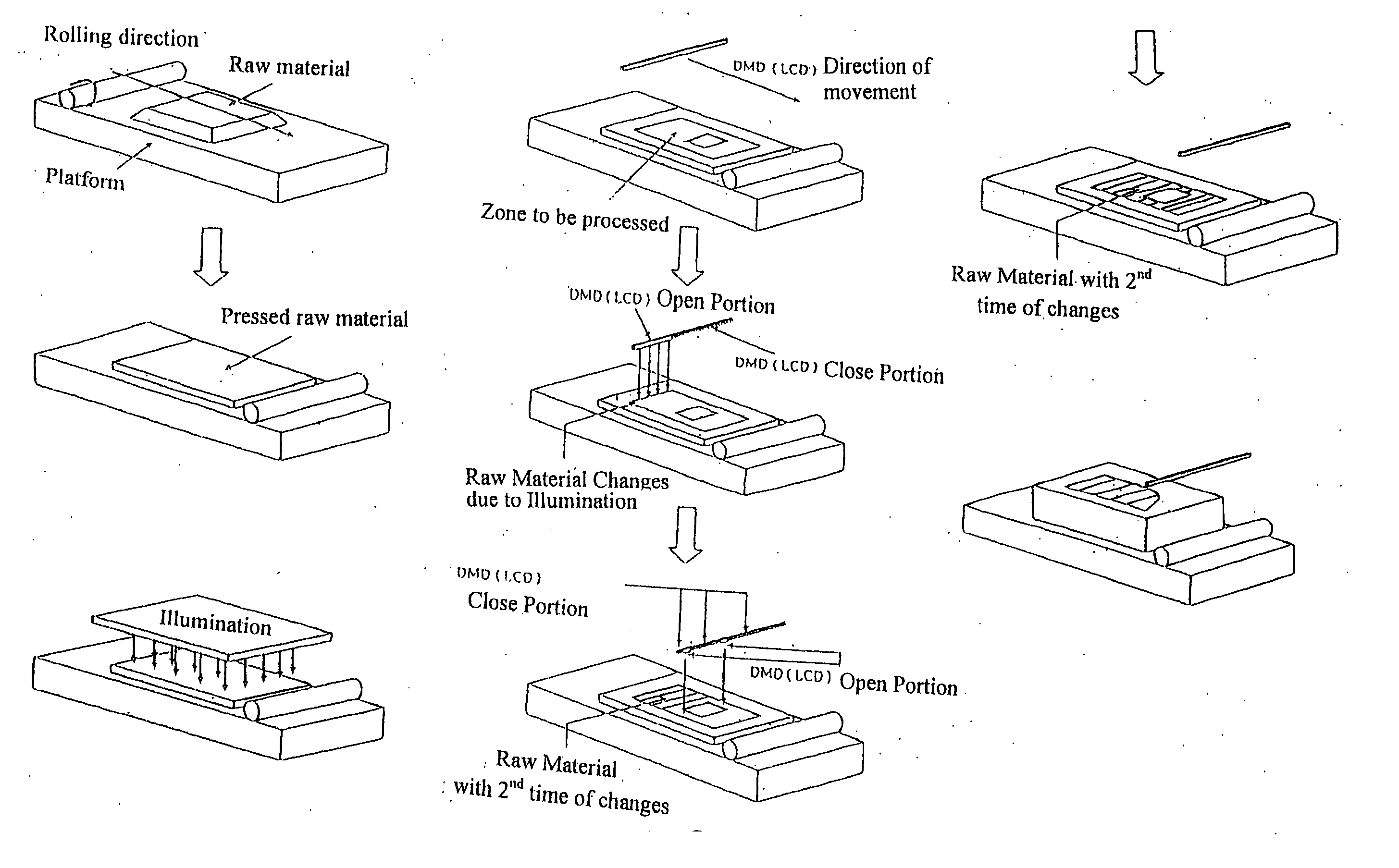
[0065] As shown in FIG. 10, the method of rapid prototyping of the present invention includes the following steps;

[0066] (1) rolling raw material onto a defined zone;

[0067] (2) illuminating the raw materials cause a first time of physical or chemical changes;

[0068] (3) using more powerful linear light source with cooperation of portable Digital Micromirror Device (DMD) to scan the selected zones of the material to cause a second time of physical or chemical changes;

[0069] (4) repeating pre-set times of the step (1) to (3) and establishing connection between layers of the 2-D images;

[0070] (5) removing the raw material from the object with the second time of change so as to obtain a solid work piece.

second embodiment

[0071] As shown in FIG. 11, the method of rapid prototyping of the present invention includes the following steps;

[0072] (1) rolling raw material onto a defined zone;

[0073] (2) illuminating the raw materials by electronic beams to cause a first time of physical or chemical changes;

[0074] (3) using more powerful linear light source with cooperation of portable Digital Micromirror Device (DMD) to scan the selected zones of the material to cause a second time of physical or chemical changes;

[0075] (4) repeating pre-set times of the step (1) to (3) and establishing connection between layers of the 2-D images;

[0076] (5) removing the raw material from the object with the second time of change so as to obtain a solid work piece.

third embodiment

[0077] As shown in FIG. 12, the method of rapid prototyping of the present invention includes the following steps;

[0078] (1) rolling raw material onto a defined zone;

[0079] (2) heating the raw materials to cause a first time of physical or chemical changes;

[0080] (3) using more powerful linear light source with cooperation of portable Digital Micromirror Device (DMD) to scan the selected zones of the material to cause a second time of physical or chemical changes;

[0081] (4) repeating pre-set times of the step (1) to (3) and establishing connection between layers of the 2-D images;

[0082] (5) removing the raw material from the object with the second time of change so as to obtain a solid work piece.


PUM

PropertyMeasurementUnit
energyaaaaaaaaaa
physicalaaaaaaaaaa
chemical changeaaaaaaaaaa

Abstract

A method for rapid prototyping by using linear light as sources employs DLP (Radiation Hardening Formation) or LCD, together with the portable devices and linear light source to treat the raw material in two stages. The first stage is to spread the raw material to a selected zone by nozzles or rollers and illuminating the material to let the material being processed and have physical o mechanical changes. The second stage is to use more powerful linear light source with the cooperation of the portable DMD (Digital Micromirror Device) or LCD (Liquid Crystal Display) to illuminate the material to make it have a second times of physical o mechanical changes. By the piling up the layers of the material, a complete 3-D work piece is obtained.

Description

FIELD OF THE INVENTION [0001] The present invention relates to a method for rapid prototyping by using linear light as sources and piling layers of 2-D images to be a 3-D image. BACKGROUND OF THE INVENTION [0002] Typically, a complete process for developing a new product from design, making a prototype, management of production processes, mass production to introducing the product to the market, there always need a prototype for evaluation and examination. Thus, a prototype that is easily manufactured and amended is an important factor for a successful product. How to manufacture the prototype that meets needs is crucial for not spending too much manufacturing cost. [0003] There are numerous methods available for prototype production such as the conventional manual production, CNC milling and carving machine. As for the conventional manual model production, except for experiences, it lacks precision. The CNC milling or carving machine are also confined to the types of chucks, bits o...

Claims


Application Information

Patent Timeline
Patent Type & Authority Applications(United States)
IPC IPC(8): G06F19/00
CPCB29C67/0059B29C67/0066B29C67/0077B29C64/112B29C64/135B29C64/153B33Y10/00B33Y30/00
Inventor HUANG, SHENG-JYEWANG, CHENG-CHIENLEE, SEN-YUNGWANG, CHUIH-KUANWANG, CHUN-SHANCHEN, CHUH-YUNGCHEN, CHIEH-LILAI, WEI-SIANGHSIEH, CHENLEU, TZONG-SHINGCHENG, CHUN-I
Owner NAT CHENG KUNG UNIV
Why Eureka
Try Eureka