Control apparatus for dry sump type internal combustion engine
a control apparatus and internal combustion engine technology, applied in the direction of machines/engines, electric control, auxiliary lubrication, etc., can solve the problems of increasing pump mechanical loss and pump work, and increasing power consumption with an increase in engine speed. , to achieve the effect of reducing nox density, increasing energy consumption, and increasing ventilation
- Summary
- Abstract
- Description
- Claims
- Application Information
AI Technical Summary
Benefits of technology
Problems solved by technology
Method used
Image
Examples
first embodiment
[Configuration of First Embodiment]
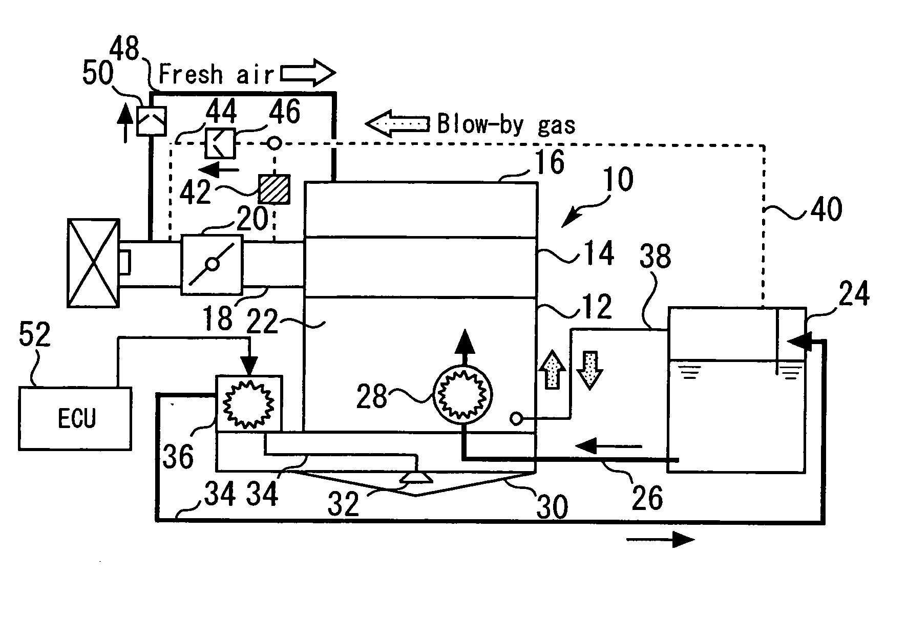
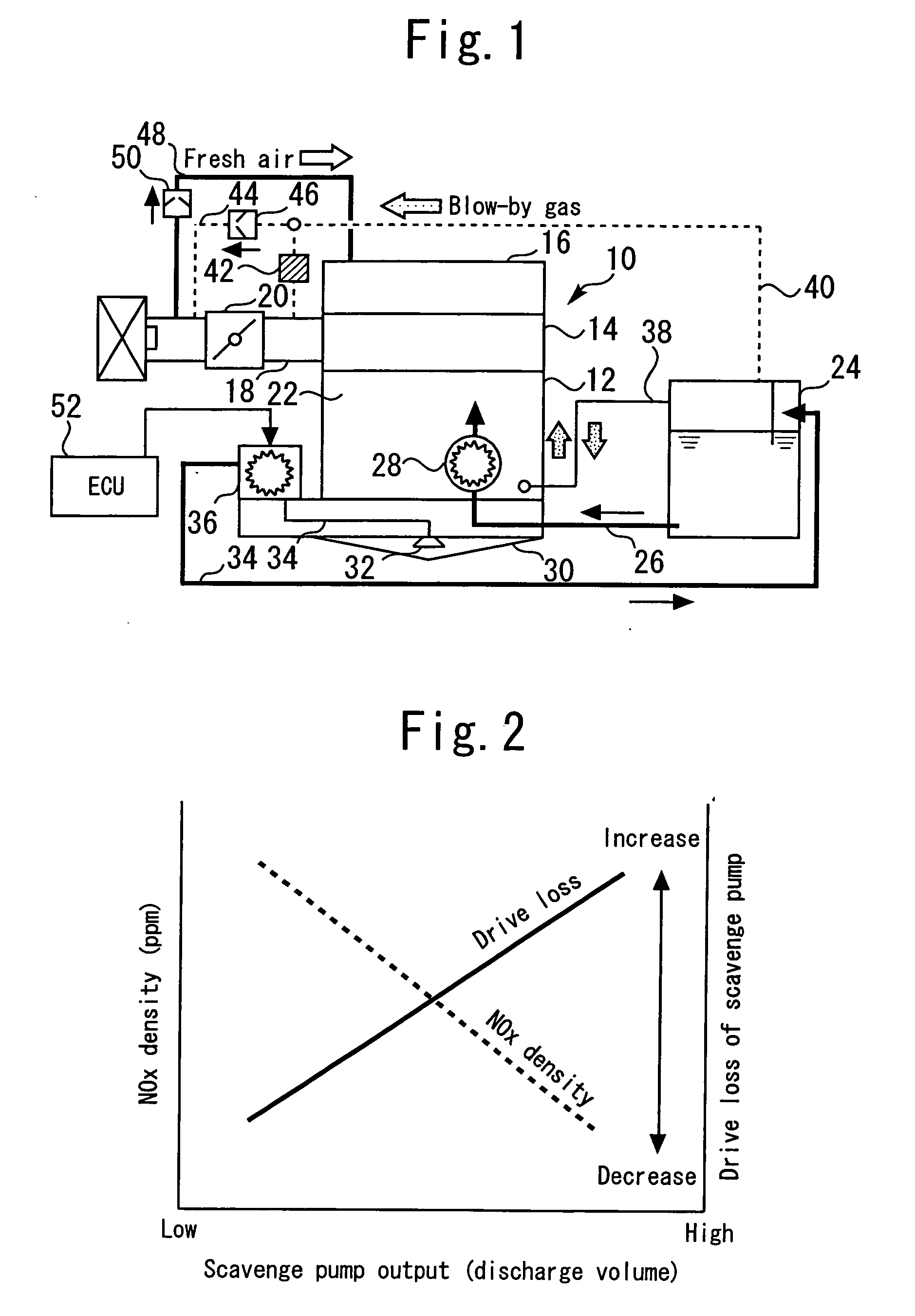
[0031]FIG. 1 illustrates the configuration of a dry sump type internal combustion engine according to a first embodiment of the present invention. The internal combustion engine 10 shown in FIG. 1 includes a cylinder block 12. A cylinder head 14 is mounted on the top of the cylinder block 12. A head cover 16 is mounted on the top of the cylinder head 14. The cylinder head 14 communicates with an intake path 18. The intake path 18 is provided with a throttle body 20, which is positioned downstream of an air cleaner.
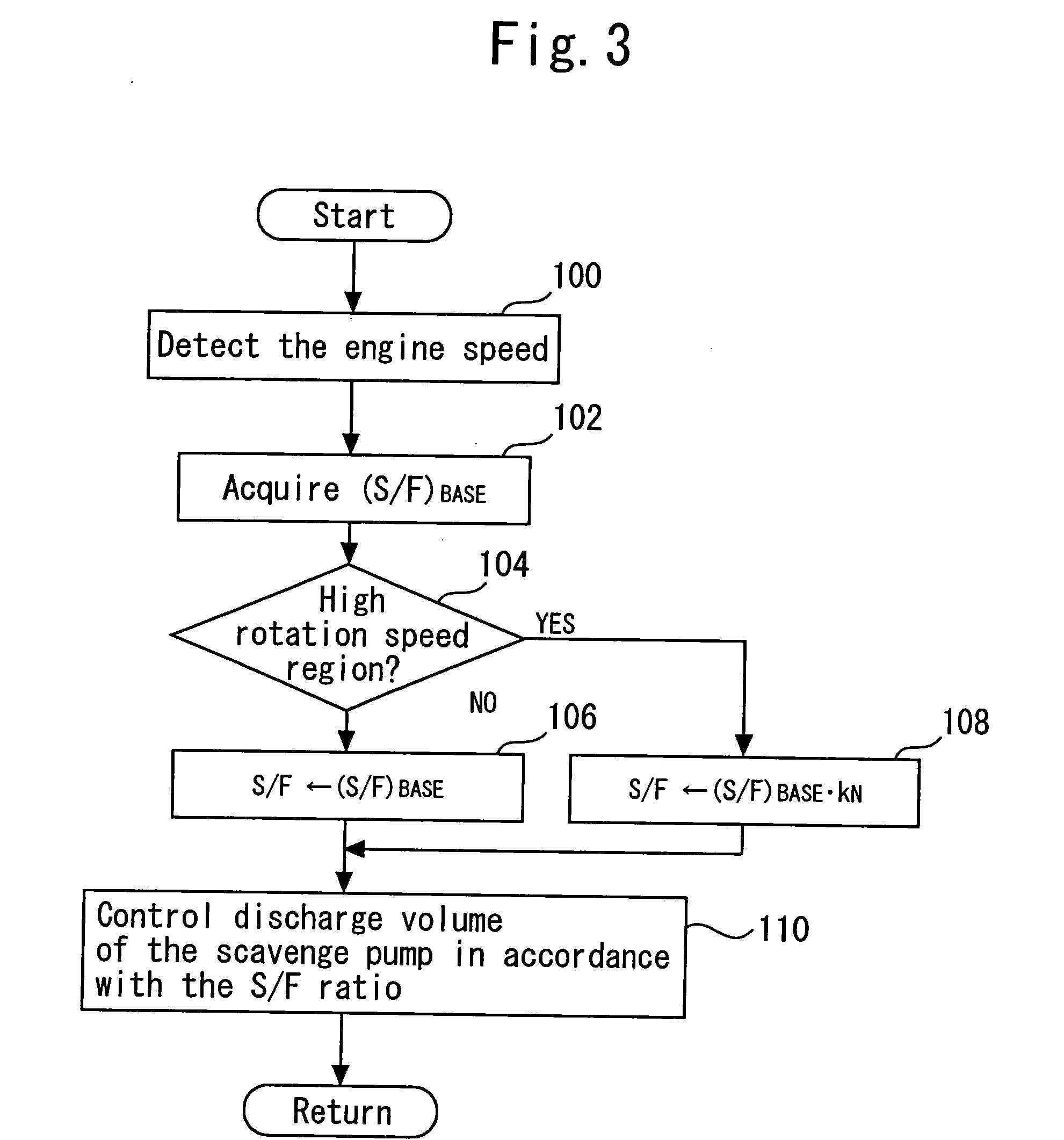
[0032] A crank chamber 22 is formed within the cylinder block 12. The crank chamber 22 is positioned below a piston (not shown). The system according to the present embodiment includes an oil tank 24, which stores the oil that is to be supplied to various sections of the internal combustion engine 10. The bottom of the oil tank 24 communicates with one end of an oil supply pipe 26. The remaining end of the oil supply pipe 26 communicate...
second embodiment
[0064] A second embodiment of the present invention will now be described with reference to FIG. 8.
[0065] The system according to the present embodiment is configured the same as the first embodiment except that a NOx density sensor is incorporated to detect the NOx density in the crank chamber 22. The first embodiment, which has been described earlier, changes the S / F ratio in accordance with the engine speed. The system according to the present embodiment changes the S / F ratio in accordance with the NOx density in the crank chamber 22 as well as the engine speed.
[0066]FIG. 8 is a flowchart illustrating a routine that the ECU 52 according to the present embodiment executes to implement the above functionality. When the present embodiment is described with reference to FIG. 8, steps identical with those described with reference to FIG. 3 for the first embodiment are designated by the same reference numerals as their counterparts and omitted from the description or briefly describe...
PUM
 Abstract
Description
Claims
Application Information
 - R&D
- Intellectual Property
- Life Sciences
- Materials
- Tech Scout
- Unparalleled Data Quality
- Higher Quality Content
- 60% Fewer Hallucinations
Browse by: Latest US Patents, China's latest patents, Technical Efficacy Thesaurus, Application Domain, Technology Topic, Popular Technical Reports.
© 2025 PatSnap. All rights reserved.Legal|Privacy policy|Modern Slavery Act Transparency Statement|Sitemap|About US| Contact US: help@patsnap.com


