System for removing plastic from recycled material

a recycling material and plastic technology, applied in the field of systems, can solve the problems of high volume of separated and removed quantities, unavoidable, and dependencies on relative mass

Inactive Publication Date: 2006-05-18
HAWKER CORP
View PDF8 Cites 14 Cited by
  • Summary
  • Abstract
  • Description
  • Claims
  • Application Information

AI Technical Summary

Benefits of technology

[0006] Just prior to the point where the material on the belt passes under the vacuum hose end e.g. a couple of feet prior, the material is agitated e.g. using a roller or rotor with slats or flutes that rapidly bumps the bottom of the belt and bounces the material conveyed on the top of the belt. Because the plastic is lighter than the vegetation material being conveyed, it rises to the top and is most susceptible to the overlying vacuum. The drawing and vacuuming effect from the material of the belt underlying the hose end is determined by the air flow through the tube and the spacing of the hose end from the material on the belt. The top most material i.e. the closest to the tube end, is thus most effected.
[0007] An operator stationed at the open end of the tube overlying the belt can view the effect of the suction and adjust the spacing of the tube end. The operator thus is able to maintain a delicate balance as between allowing too much plastic to cross the tube end (the tube end needs to be lowered) and having too much of the vegetation drawn into the tube end (the tube end needs to be raised).

Problems solved by technology

A problem with the procedure currently in use for separating out the plastic, is the dependency on relative mass as between the plastic and the various types of yard debris.
It is perhaps unavoidable that the air suction draw for removing the plastic also draws off a portion of the otherwise quite acceptable yard debris material.
Such criteria results in a high volume of separated and removal of a quantity of the lighter yard debris along with the desired plastic.
Because the plastic is lighter than the vegetation material being conveyed, it rises to the top and is most susceptible to the overlying vacuum.

Method used


Image

  • System for removing plastic from recycled material
  • System for removing plastic from recycled material
  • System for removing plastic from recycled material

Examples


Embodiment Construction

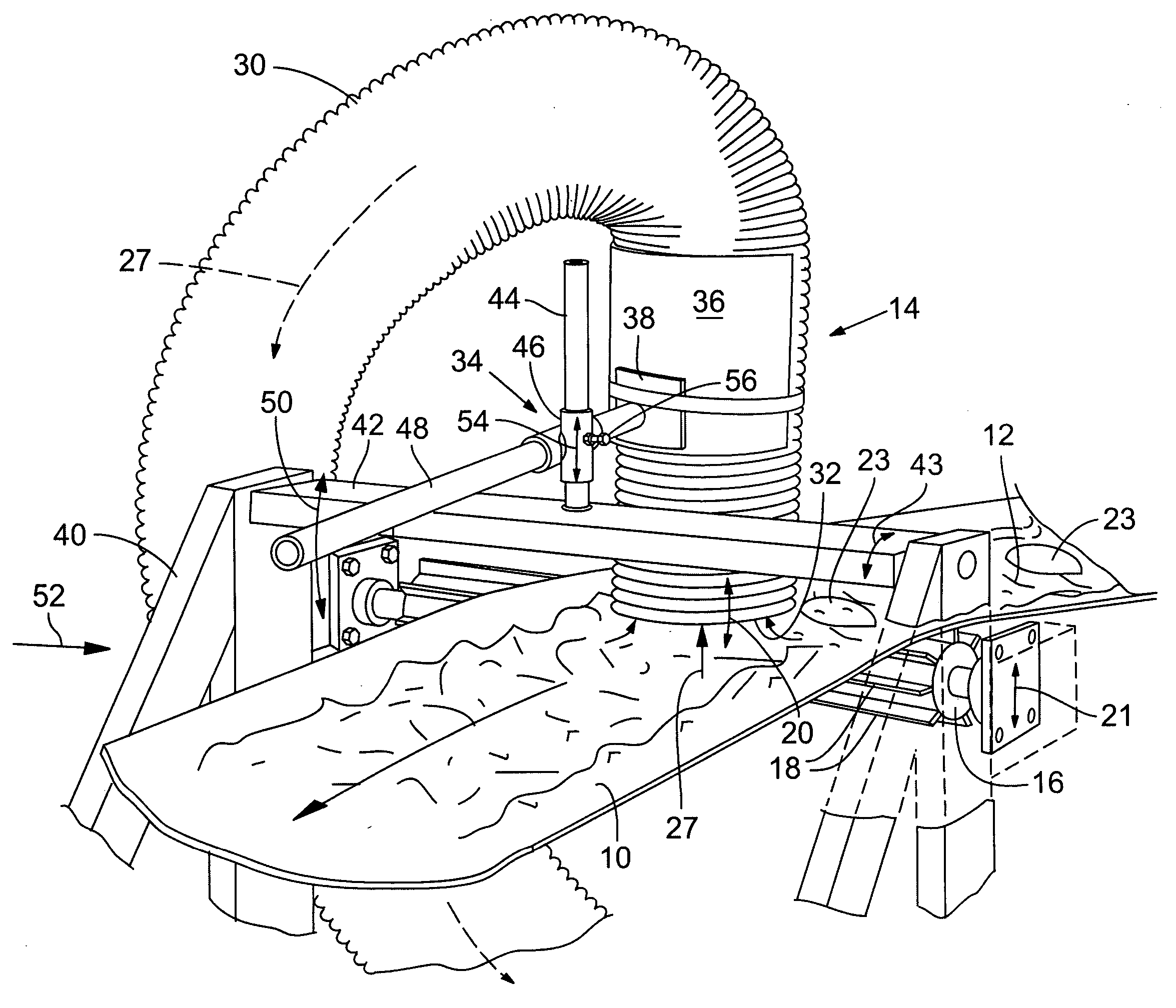
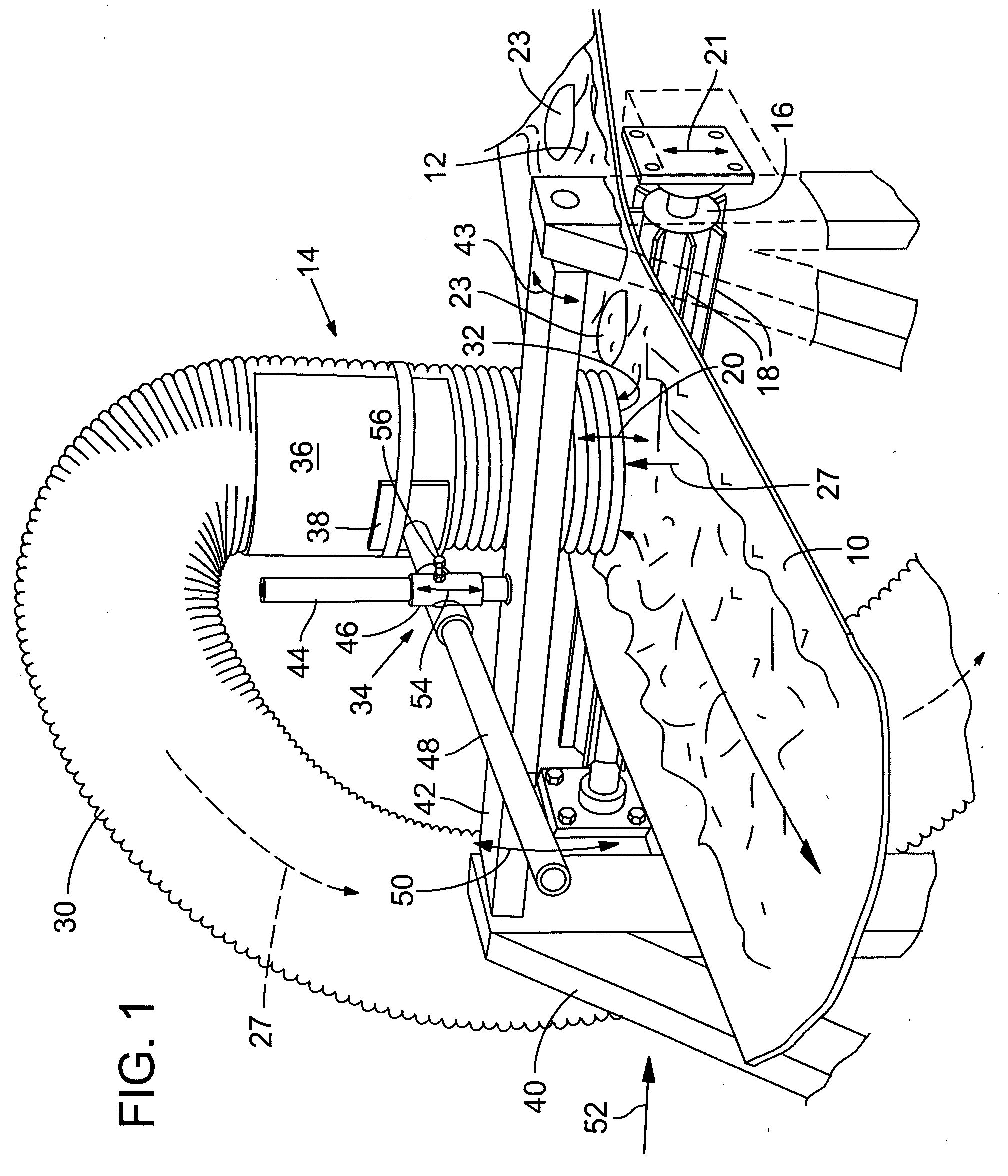
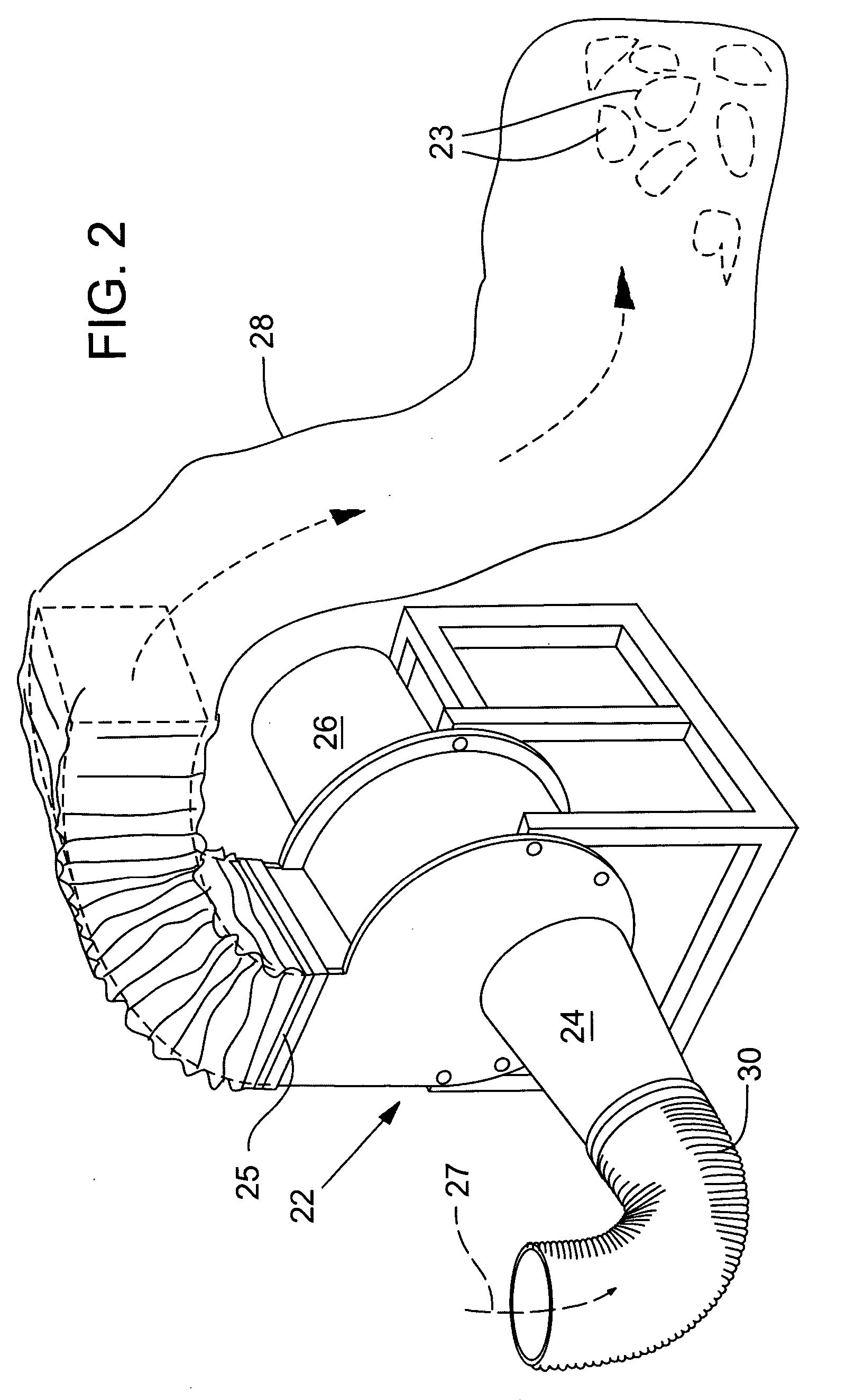
[0012]FIGS. 1 and 2 illustrate an embodiment of the invention. FIG. 1 shows a trough-type conveyor belt 10 conveying ground up yard debris 12. The yard debris 12 typically has been through prior processing step(s) including a grinding process that e.g. reduces tree limbs and the like to chunks of vegetation referred to herein sometimes as bark chips. The bark chips have further been separated into size categories by screening which typically includes placing the bark chips on one end of an inclined vibrating screen where small bark chips pass through the screen and the larger size chips are vibrated along the screen length and deposited off the screen end. This latter debris-type is referred to as bark chip overs or simply as overs. Plastic bags that have been shredded by the prior grinding operation are largely contained in the bark chips' overs. It is the bark chip overs with plastic pieces that make up the material 12 of FIG. 1 and the operation of the apparatus of FIGS. 1 and 2 ...


PUM

PropertyMeasurementUnit
diameteraaaaaaaaaa
plasticaaaaaaaaaa
sizeaaaaaaaaaa

Abstract

A system for separating pieces of plastic bag from ground yard debris and the like, e.g., asphalt shingles. A conveyor conveys the debris material along a conveyor path and an agitator bounces the conveyor to cause the lighter plastic to reposition to the top of the material on the conveyor. A suction tube end is positioned over the debris material following agitation to draw the plastic off the top of the material. The tube end is selectively adjustable to enable discriminate suction effect to draw off a maximum amount of plastic and a minimal amount of nonplastic recyclable debris.

Description

FIELD OF THE INVENTION [0001] This invention relates to a system that removes plastic from recycled materials and more particularly the removal of pieces of plastic film resulting from shredding of plastic bags, e.g., during a recycling of yard debris. BACKGROUND OF INVENTION [0002] It is common practice for communities to provide for recycling of yard debris such as grass, weeds, bush trimmings, tree branches and so on. These materials are collected e.g. from home owners, shredded, screened and redistributed e.g. as ground cover, rather than filling in-ground disposal sites. However, a constant problem with this recycling process is the presence of plastic film among the yard debris. This is believed due to the practice of homeowners collecting yard debris in large plastic bags and dumping the bags filled with the yard debris into designated recycling bins. Plastic bags get shredded and screened with the yard debris and if not removed gets deposited with the yard debris for redistr...

Claims


Application Information

Patent Timeline
Patent Type & Authority Applications(United States)
IPC IPC(8): B65G27/00
CPCB07B4/08B29B17/02B29B2017/0227B29B2017/0241B29K2095/00B29K2105/065B29K2711/00B29L2031/7128B65G47/5195Y02W30/52Y02W30/62
Inventor POSNER, OREN R.POSNER, SUSAN C.JONES, BILL
Owner HAWKER CORP
Why Eureka
Try Eureka