Liquid metal droplet generator

a technology of liquid metal droplet and generator, which is applied in the direction of manufacturing converters, liquid transfer devices, furnaces, etc., can solve the problems of limit the velocity with which droplets may be ejected, and the pressure available via this method is not as great as would be desired

Inactive Publication Date: 2006-05-18
PUREX
View PDF7 Cites 32 Cited by
  • Summary
  • Abstract
  • Description
  • Claims
  • Application Information

AI Technical Summary

Problems solved by technology

However, there appear to be limits to the velocity with which the droplets may be ejected, and to the ultimate temperature range accessible by these techniques.
Because of the mass of the membrane and its size, the pressure available via this method is not as great as would be desired, especially for the generation of the very small, high velocity droplets required in an EUV source.

Method used


Image

  • Liquid metal droplet generator
  • Liquid metal droplet generator
  • Liquid metal droplet generator

Examples


Embodiment Construction

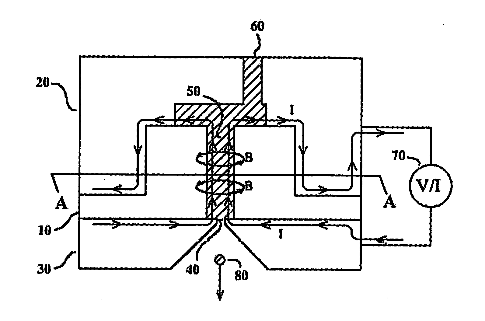
[0014] In a droplet generator the principle of magnetic compression is used to force liquid metal through a small nozzle, or orifice. However, no barrier membrane is required, as the magnetic field due to an electric current within the liquid metal itself acts on this current to generate internal pressure. This effect is referred to as a “pinch” when applied to the passage of current through a plasma, but in this case the inward pinch force is generated by conduction electrons within the liquid metal. The pinch force produces peak pressure on the axis of the liquid metal conductor, where an orifice is located in order to eject liquid metal droplets. The invention therefore only applies to the generation of droplets out of liquids with high electrical conductivity, implying liquid metals.

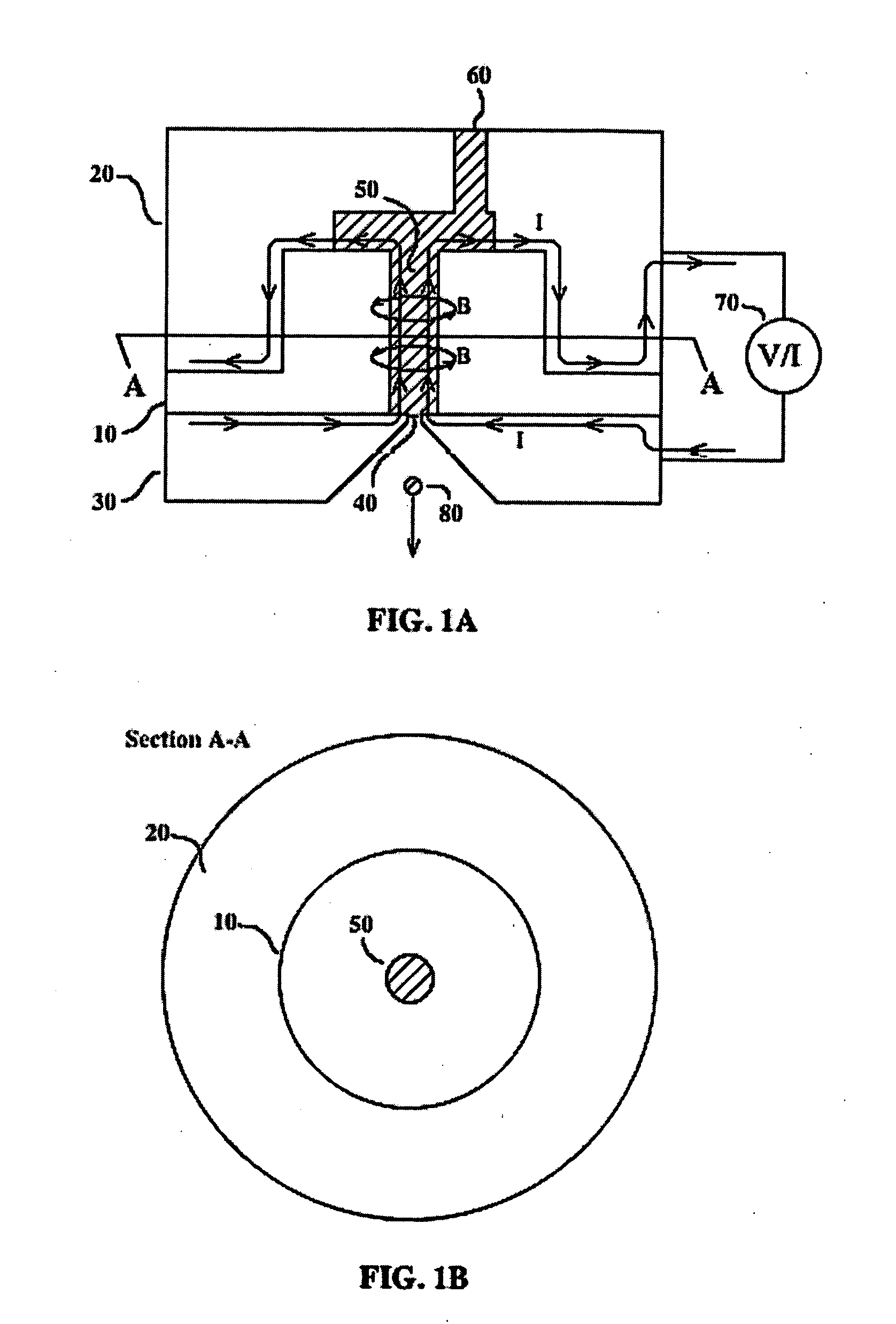
[0015] One embodiment of the invention is illustrated with reference to FIGS. 1A and 1B. The temperature of the apparatus is raised to the point where the subject metal is liquid. The liquid metal 5...


PUM

PropertyMeasurementUnit
wavelengthaaaaaaaaaa
lengthaaaaaaaaaa
radiusaaaaaaaaaa

Abstract

Small, high velocity liquid metal droplets are produced for applications that require the accurate and remote placement of small quantities of a metal. The magnetic pressure of current flowing through liquid metal is used to force small quantities of liquid metal through an orifice. Examples of applications are to feed metal fuel into plasma extreme ultraviolet sources, and to place solder bumps on an integrated circuit prior to the attachment of connections.

Description

CROSS REFERENCE TO RELATED APPLICATION [0001] This application claims priority based on provisional application Ser. No. 60 / 621,895 filed Oct. 25, 2004, which is hereby incorporated by reference in its entirety.FIELD OF THE INVENTION [0002] This invention relates to the production of small, high velocity liquid metal droplets for use in applications that require the accurate and remote placement of small quantities of a metal. The magnetic pressure of current flowing through liquid metal is used to force small quantities of liquid metal through an orifice. Examples of applications are to feed metal fuel into plasma extreme ultraviolet sources, and to place solder bumps on an integrated circuit prior to the attachment of connections. BACKGROUND OF THE INVENTION [0003] There are several applications which require the accurate and remote placement of small quantities of liquid metal. One of these is in the application of solder “bumps” to the terminals of integrated circuits where pure...

Claims


Application Information

Patent Timeline
Patent Type & Authority Applications(United States)
IPC IPC(8): B22D41/50B22D41/00B67D7/42B67D7/72B67D7/80
CPCB22D39/003B23K28/00H01L24/11H01L2224/13099H01L2924/01013H01L2924/01015B41J2202/04H01L2924/14H01L2924/30107H01L2924/01005H01L2924/01006H01L2924/01033H01L2924/014H01L2924/01082
Inventor MCGEOCH, MALCOLM W.
Owner PUREX
Why Eureka
Try Eureka