Ergonomically designed portable seat cushion

a seat cushion and elastic technology, applied in the field of portable seat cushions, can solve the problems of no seat cushion having a structure in the prior art, and achieve the effects of reducing the pressure on the ischial tuberosities and the coccyx, minimizing the blockage of blood pressure circulation, and maximizing the contact area

Inactive Publication Date: 2006-05-18
KIM JUNGIN
View PDF10 Cites 14 Cited by
  • Summary
  • Abstract
  • Description
  • Claims
  • Application Information

AI Technical Summary

Benefits of technology

[0011] It is the purpose of this invention to provide a portable seat cushion that minimizes blocking of blood pressure circulation, stress and pain in the femoral region due to sitting on a seat for an extended period, such as long range driving and international flights in the economy section. The overall shape of the cushion resembles human lungs connected to each other at the upper part with an upper surface that is flat with the exception of two wing portions. The wings are in a convex shape. The cushion is made of EP (Ethylene-Propylene Copolymer) rubber foam. A straight shallow center groove is concavely developed on the upper surface of the cushion, dividing it into two geometrically identical shapes. Air can move through this groove to remove sweat and other organic vapors accumulated during the long periods of sitting on the same seat. Two concave grooves, resembling hemi-oval shapes being cut along the long center axis thereof are developed on the flat upper surface of the seat cushion to receive

Problems solved by technology

None of the prior art provides a seat cushion having a structure for minimizing blood pressure build up, stress and pai

Method used


Image

  • Ergonomically designed portable seat cushion
  • Ergonomically designed portable seat cushion
  • Ergonomically designed portable seat cushion

Examples


Embodiment Construction

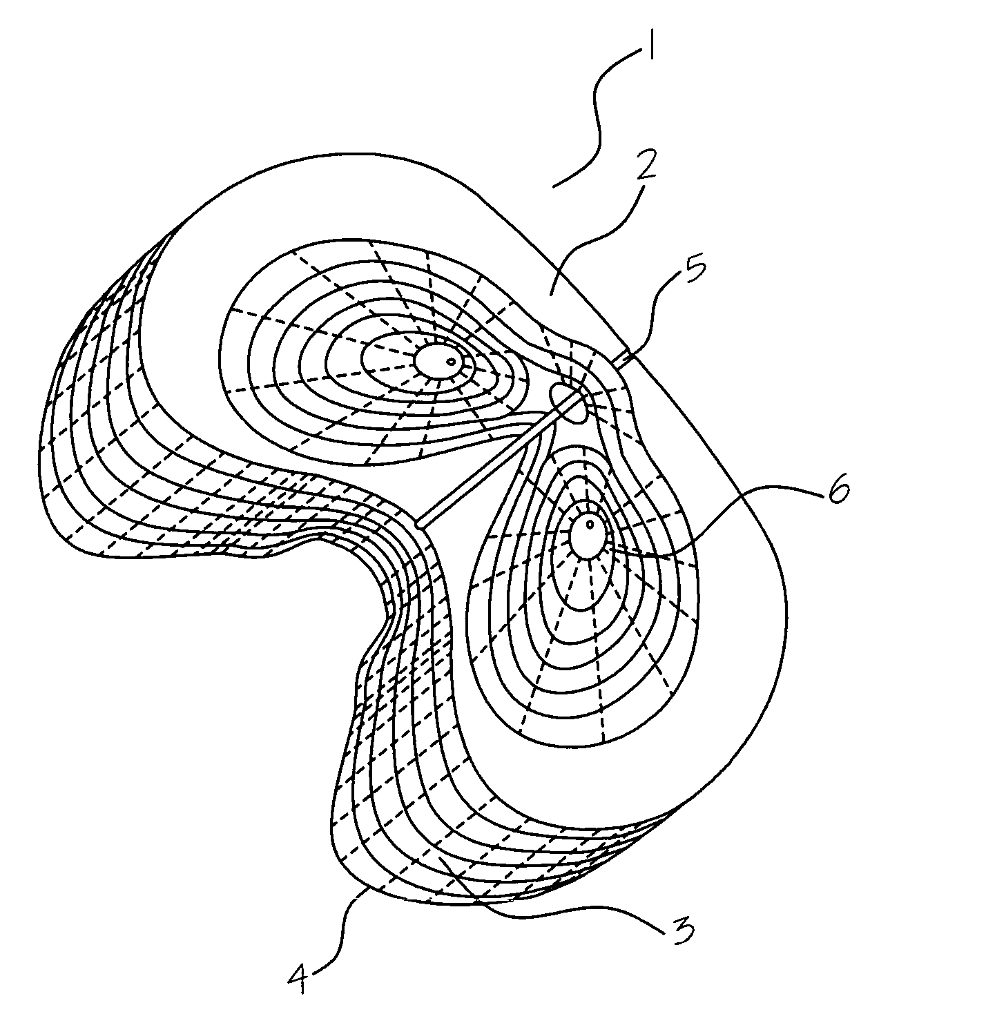
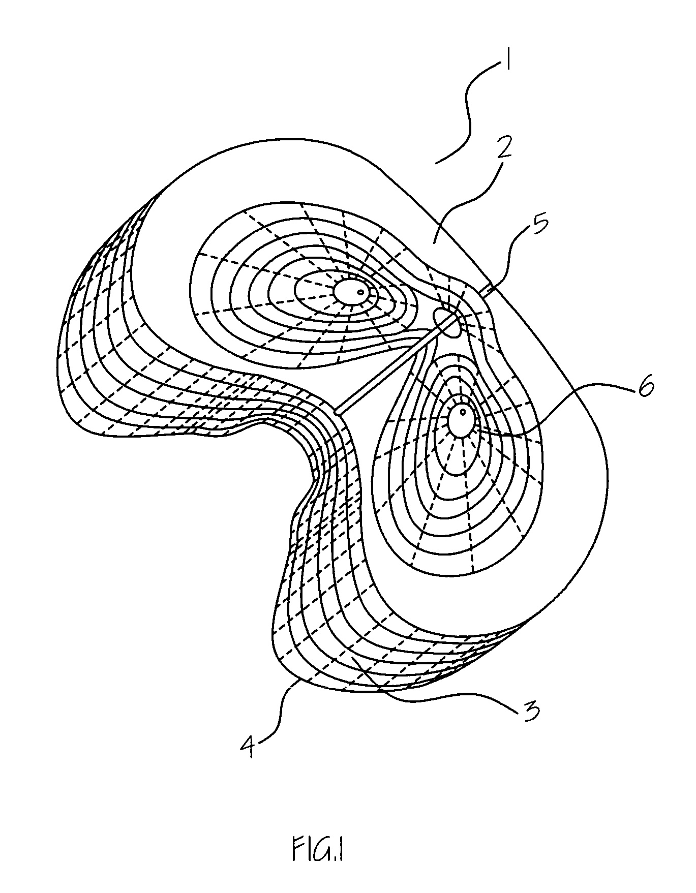
[0020] Referring to FIG. 1 to FIG. 4, the overall shape of the seat cushion (1) resembles a human lungs connected to each other at the upper part with an upper surface (2) that is flat except two wing portions (3). The wing portions (3) are in a convex shape and the tip (4) is in round shape. The seat cushion (1) is made of EP (Ethylene-Propylene Copolymer) rubber foam.

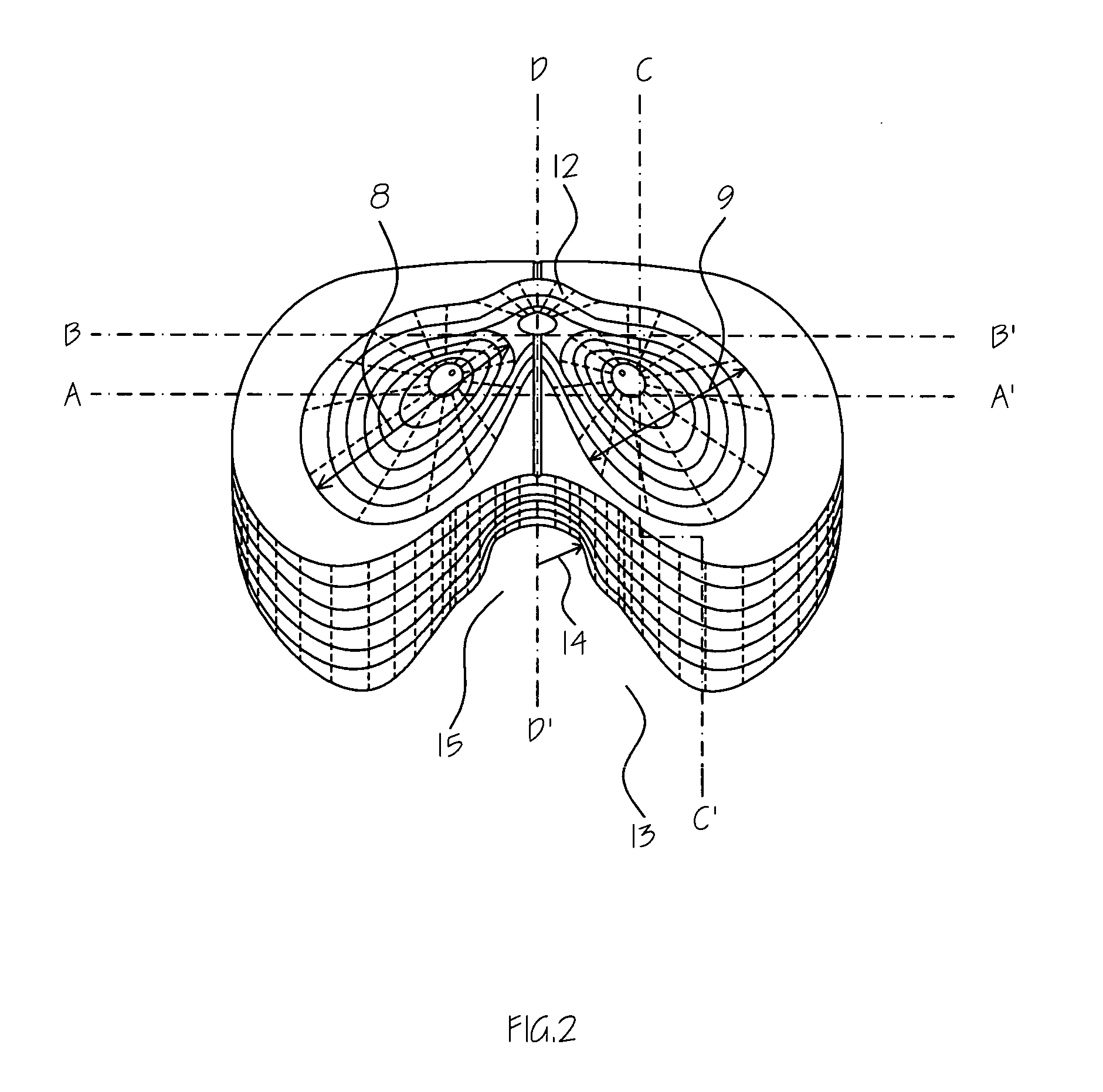
[0021] A straight shallow center groove (5) is concavely developed on the upper surface of the cushion dividing it into two geometrically identical shapes. Air moves through this groove (5) to remove sweat and other organic vapors accumulated during the long period of time on the same seat. The center groove (5) is hemi-tube shape of 4.76 mm width by 2.38 mm depth.

[0022] Two concave grooves (6), resembling hemi-oval shape of being cut along the long center axis thereof, are developed on the flat upper surface (2) of the seat cushion (1) to receive ischial tuberosities of a user. The depth (7) of the ischial tuberosi...


PUM


Abstract

A portable cushion that minimizes the blocking of blood circulation, stress, and pain in the femoral region caused by sitting on a chair for long hours or an extended time is provided. The overall shape of the cushion resembles human lungs connected to each other at the upper part with an upper surface that is flat, except for two wing portions. The wings are in a convex shape. The cushion is made of EP (Ethylene-Propylene Copolymer) rubber foam. A straight shallow center groove is concavely developed on the upper surface of the cushion along the direction of the wings. Two concave grooves, resembling hemi-oval shapes being cut along the long center axis thereof are developed on the flat upper surface of the seat cushion to receive ischial tuberosities of a user. A shell-shaped concave groove for receiving the coccyx of the user is developed on the rear part of the flat upper surface of the cushion between the two hemi-oval shape grooves. The front side of the cushion, between the two wings, is caved in for receiving and positioning of genitals of the user. The unique geometry of the cushion reduces the pressure to the ischial tuberosities and the coccyx of a user by maximizing the contact area and distribute the user's weight throughout the surface, while minimizing the blocking of blood circulation by minimizing the contact area of the wings of the cushion and the rear part of the thighs of the user.

Description

BACKGROUND OF THE INVENTION [0001] 1. Field of the Invention [0002] Current application relates to a portable elastic rubber cushion for providing a comfortable pose to a user who is sitting on a seat for an extended period. [0003] 2. Description of the Prior Art [0004] U.S. Pat. No. 4,132,228 to Green illustrates a comfort support seat cushion assembly providing even pressure distribution on the gluteal region with pressure relief for the ischial tuberosities, coccyx, and perineum. The overall shape of the seat cushion is the bottom face of a common chair with a hole on the perineum-contacting portion. Whole surface is concavely carved. [0005] U.S. Pat. No. 4,643,481 to Saloff, et al. illustrates a seat system comprised of a base and cushion for a wheel chair. The base has a specially contoured support surface including a forward section and a rearward section. The rearward section has a pair of wings surrounding a void over which the user's ischia and coccyx are to be positioned a...

Claims


Application Information

Patent Timeline
IPC IPC(8): A47C7/02
CPCA47C7/022A61G2005/1045A61G2005/1091A61G5/1045A61G5/1091A47C7/029A47C27/00
Inventor KIM, JUNGIN
Owner KIM JUNGIN
Why Eureka
Try Eureka