
Latency tolerant system for executing video processing operations

Active Publication Date: 2006-05-18
NVIDIA CORP
View PDF99 Cites 133 Cited by
  • Summary
  • Abstract
  • Description
  • Claims
  • Application Information

AI Technical Summary

Benefits of technology

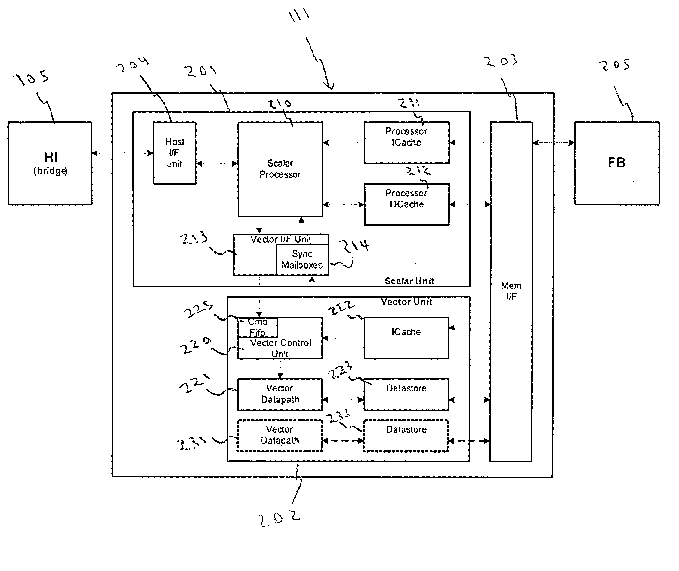
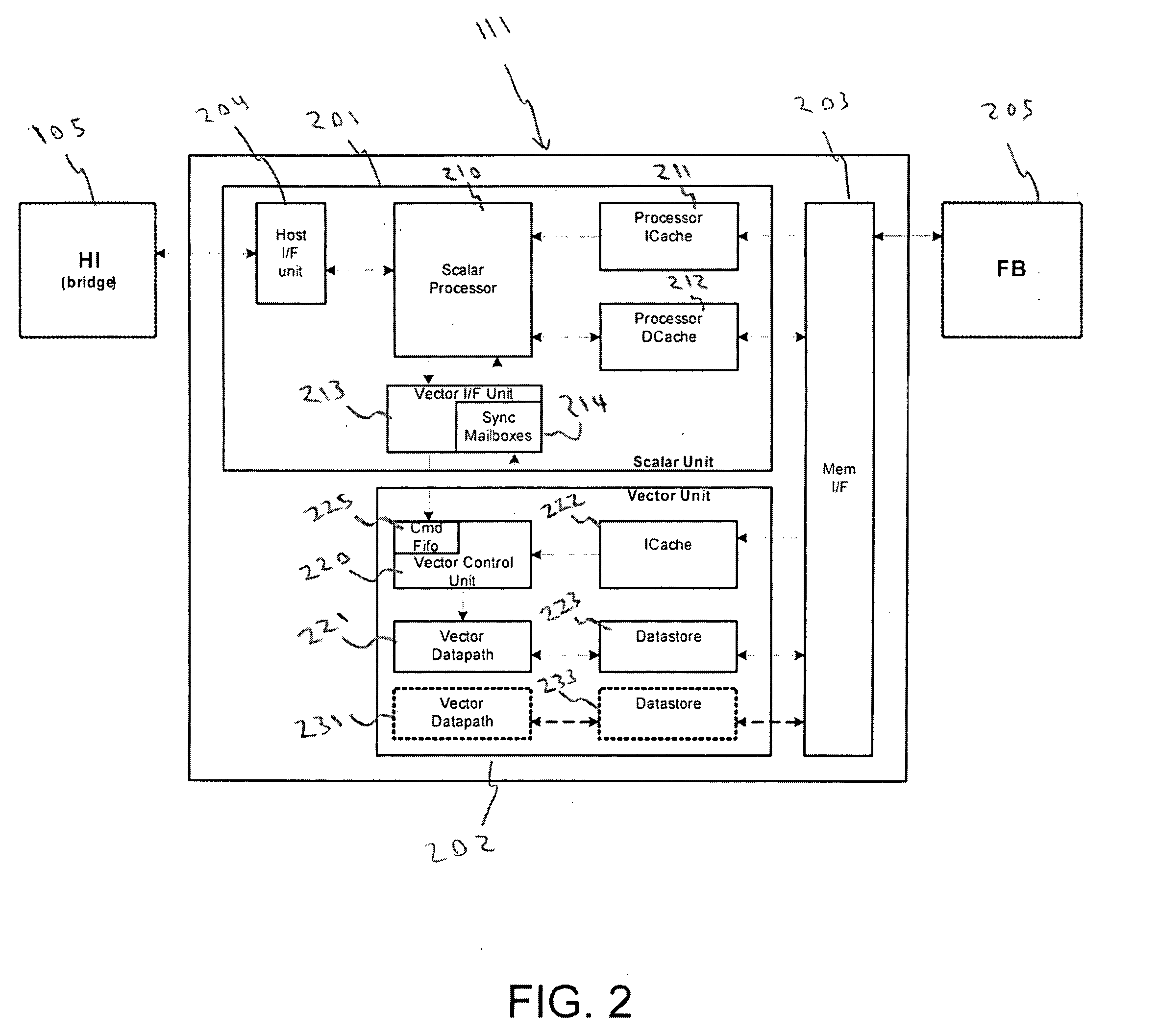
[0010] Embodiments of the present invention provide a new video processor system that supports sophisticated video processing functions while making efficient use of integrated circuit silicon die area, transistor count, memory speed requirements, and the like. Embodiments of the present invention maintain high compute density and are readily scalable to handle multiple video streams.
[0012] In one embodiment, the vector execution unit is configured to operate asynchronously with respect to the scalar execution unit by accessing the command FIFO to operate on the demand driven basis. The demand driven basis can be configured to hide a latency of a data transfer from the different memory locations (e.g., frame buffer memory, system memory, cache memory, etc.) to the command FIFO of the vector execution unit. The command FIFO can be a pipelined FIFO to prevent stalls of the vector execution unit.

Problems solved by technology

The problem with providing such sophisticated video processor functionality is the fact that a video processor having a sufficiently powerful architecture to implement such functions can be excessively expensive to incorporate into many types of devices.
The more sophisticated the video processing functions, the more expensive, in terms of silicon die area, transistor count, memory speed requirements, etc., the integrated circuit device required to implement such functions will be.
Accordingly, prior art system designers were forced to make trade-offs with respect to video processor performance and cost.
Prior art video processors that are widely considered as having an acceptable cost / performance ratio have often been barely sufficient in terms of latency constraints (e.g., to avoid stuttering the video or otherwise stalling video processing applications) and compute density (e.g., the number of processor operations per square millimeter of die).
Furthermore, prior art video processors are generally not suited to a linear scaling performance requirement, such as in a case where a video device is expected to handle multiple video streams (e.g., the simultaneous handling of multiple incoming streams and outgoing display streams).

Method used


Image

  • Latency tolerant system for executing video processing operations
  • Latency tolerant system for executing video processing operations
  • Latency tolerant system for executing video processing operations

Examples


Embodiment Construction

[0020] Reference will now be made in detail to the preferred embodiments of the present invention, examples of which are illustrated in the accompanying drawings. While the invention will be described in conjunction with the preferred embodiments, it will be understood that they are not intended to limit the invention to these embodiments. On the contrary, the invention is intended to cover alternatives, modifications and equivalents, which may be included within the spirit and scope of the invention as defined by the appended claims. Furthermore, in the following detailed description of embodiments of the present invention, numerous specific details are set forth in order to provide a thorough understanding of the present invention. However, it will be recognized by one of ordinary skill in the art that the present invention may be practiced without these specific details. In other instances, well-known methods, procedures, components, and circuits have not been described in detail...


PUM


Abstract

A latency tolerant system for executing video processing operations. The system includes a host interface for implementing communication between the video processor and a host CPU, a scalar execution unit coupled to the host interface and configured to execute scalar video processing operations, and a vector execution unit coupled to the host interface and configured to execute vector video processing operations. A command FIFO is included for enabling the vector execution unit to operate on a demand driven basis by accessing the memory command FIFO. A memory interface is included for implementing communication between the video processor and a frame buffer memory. A DMA engine is built into the memory interface for implementing DMA transfers between a plurality of different memory locations and for loading the command FIFO with data and instructions for the vector execution unit.

Description

[0001] This application claims the benefit under 35 U.S.C. Section 119(e) of U.S. Provisional Application Ser. No. 60 / 628,414, filed on Nov. 15, 2004, to Gadre et al., entitled “A METHOD AND SYSTEM FOR VIDEO PROCESSING” which is incorporated herein in its entirety.FIELD OF THE INVENTION [0002] The field of the present invention pertains to digital electronic computer systems. More particularly, the present invention relates to a system for efficiently handling video information on a computer system. BACKGROUND OF THE INVENTION [0003] The display of images and full-motion video is an area of the electronics industry improving with great progress in recent years. The display and rendering of high-quality video, particularly high-definition digital video, is a primary goal of modern video technology applications and devices. Video technology is used in a wide variety of products ranging from cellular phones, personal video recorders, digital video projectors, high-definition television...

Claims


Application Information

Patent Timeline
IPC IPC(8): G09G5/39G09G5/36
CPCG06F3/14G06T1/20G09G5/37H04N19/86H04N19/82H04N19/436H04N19/61G06F9/3851G06F9/3887G06T1/60H04N19/42H04N19/423H04N19/44H04N19/85G06T1/00G09G5/36G09G5/39G06F12/0877
Inventor KARANDIKAR, ASHISHGADRE, SHIRISHLEW, STEPHEN D.
Owner NVIDIA CORP
Learn More