Electrooptic chromophores with large optical birefringence for applications at high speed and short wavelengths

Inactive Publication Date: 2006-05-18
OPTIMER PHOTONICS
View PDF7 Cites 17 Cited by
  • Summary
  • Abstract
  • Description
  • Claims
  • Application Information

AI Technical Summary

Benefits of technology

[0035] The Pockels effect can only be exhibited by materials that lack a center of symmetry. For electrooptic polymers (or polymer/chromophore blends), which are isotropic, the intrinsic symmetry is broken by electric field poling. In this situation, the polymer is heated above its glass transition temperature. A strong electric field then is applied to the material. The interaction between the field and the dipole moment of the chromophore causes the chromophores (or optically active polymer components) to align along the field. The polymer then is cooled to below its glass transition temperature with the field still applied, causing the ordering to be frozen in, creating a uniaxial material. In poled polymeric materials, the Pockels coefficient r33, is proportional to the product of the dipole moment, first hyperpolarizability, and poling field. A primary concern with materials using the Pockels effect is the rate at which the poling decays. Because the oriented (poled) material is not in a thermodynamic equilibrium state, the ordering will relax over time, leading to a reduced EO response. In guest-host materials, the rate of this decay depends on the size of the chromophore and the temperature difference between the testing temperature and the glass transition temperature of the polymer.
[0036] In the Kerr effect, the material's optical response is proportional to the square of the applied electric field. The electric field induces optical anisotropy either through molecular reorientation or alteration of the electronic structure of the medium. In the static field limit [C. J. F. Bottcher and P. Bordewijk, Theory of Electric Polarization, Elsevier Scientific Pub., 1973; W. T. Coffey and S. G. McGoldrick. “Inertial effects in the theory of dielectric and Kerr effect relaxation of an assembly of non-interacting polar molecules in strong alternating fields”. Chemical Physics, Vol. 120, pp. 1-35, (1988)], the Kerr response is: [K]=2⁢π⁢ ⁢NA405⁡[3kT⁢(ατ:ατ-3⁢αα)+2⁢Iτ:γτ:Iτ+3k2⁢T2⁢(ατ:μρ⁢μρ-αμ2)+4kT⁢μρ·βτ:Iτ]
[0037] The electrooptic response of a chromophore can be measured in a polymer matrix using a transmission technique at telecommunication wavelength of 1.55 μm, or any other desired wavelength, such as 633 nm or 405 nm. A representative method for measuring the electro-optic coefficient is described in Nahata, et al., J. Opt. Soc. Am. B, 10, 1553 (1993). In this arrangement (shown in FIG. 1), two thin electrodes are laid down on a quartz slide, with a 20 μm gap between the electrodes. The polymer is applied to cover the two electrodes and fill the gap between them, and then is dried to remove all the solvent. Typical thickness of the polymer film ranges from about 10 to about 30 μm, and is measured for each individual cell.
[0038] To measure the EO effect in polymers, the polymer is heated (if desired), and both an AC and DC voltage is applied to the electrodes. For all EO meas

Problems solved by technology

However, this increase in acceptor strength also leads to aggregation of the chromophore molecules in most polymers.
A second pressing issue for conventional

Method used


Image

  • Electrooptic chromophores with large optical birefringence for applications at high speed and short wavelengths
  • Electrooptic chromophores with large optical birefringence for applications at high speed and short wavelengths
  • Electrooptic chromophores with large optical birefringence for applications at high speed and short wavelengths

Examples


Example

Example 1

Properties of Small Chromophores

[0063] In this example, several prototypical small chromophores, along with their calculated (and measured if available) properties are presented. The values are given in Table 9. The values of μ and μβ for the experimental PFOM are taken from L.-T. Cheng, et. al., J. Phys. Chem. 95, pp. 10631 (1991). The calculated results were obtained using JAGUAR, as described above. TABLE 9Properties of Small Chromophoresexpt.calc.MoleculeAbbreviationMWλ maxFOMcalc. μβFOMo2,5 bis-trifluoromethyl aniline2,5-BTFMA229.122.950.0134 trifluoromethyl aniline4-TFMA161.137.880.0493,5 bis-trifluoromethyl aniline3,5-BTFMA229.126.580.029nitrobenzeneNB123.11˜260 nm  0.0633.780.031α,α,α trifluorotolueneAAATFT146.113.770.026N,N, dimethyl 4 nitro analineDMNA166.18407 nm0.44870.570.4254-(dimethylamino)benzonitrile4DMABN146.19 290 nm*0.19247.850.3274-(dimethylamino)-2,2,2-trifluoroacetophenone4DMATFAP189.14 356 nm*0.31276.080.4023 methyl 4amine nitrobenzene3M4ANB152.15...

Example

Example 2

EO Properties of Standard Chromophore / Polymer Blend (178-086-02)

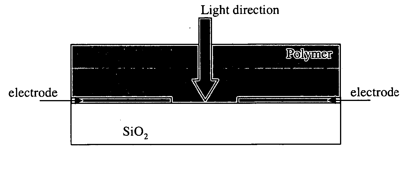
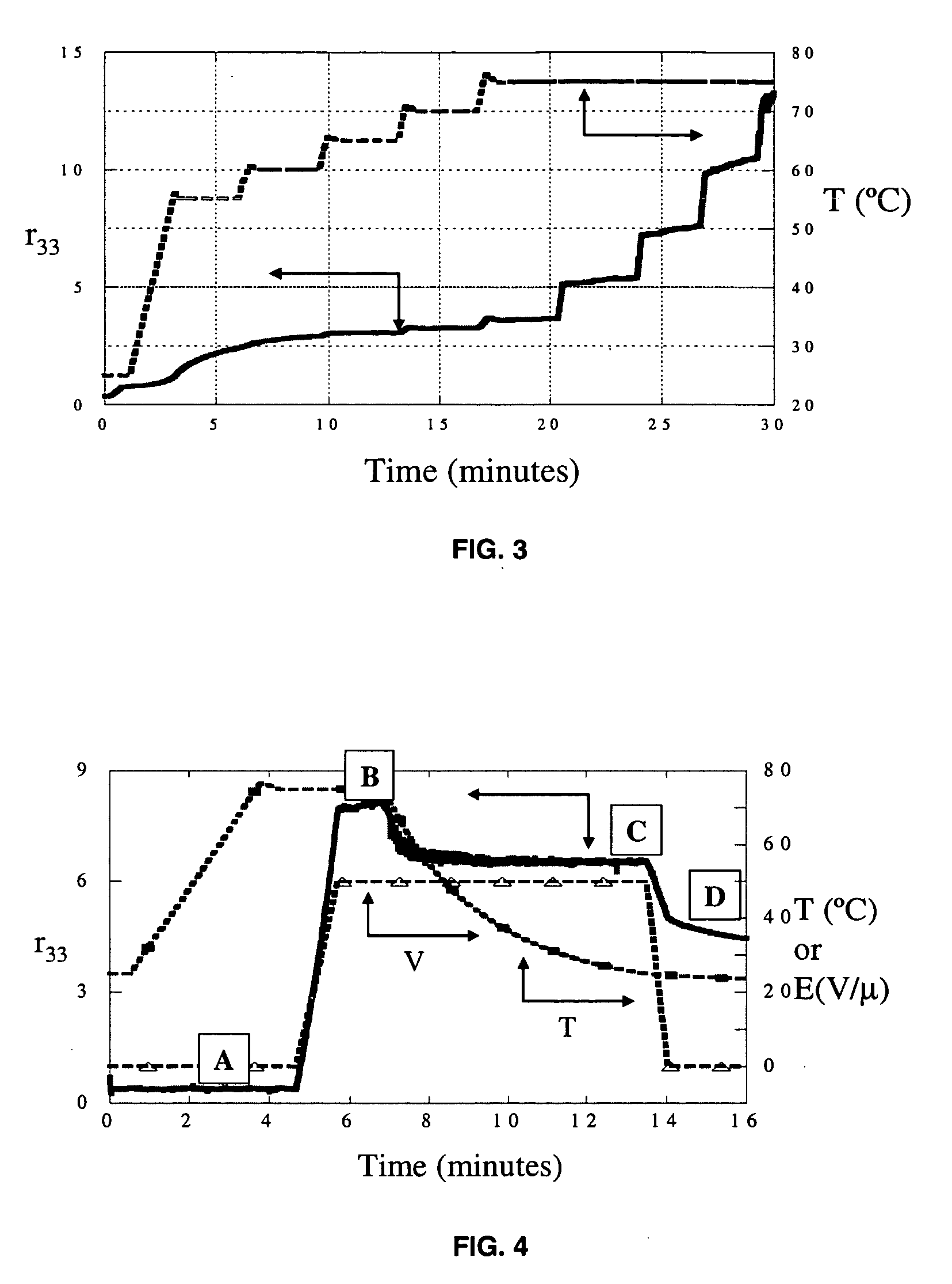
[0064] In this example we present the EO response of a standard OPI chromophore, VC8 (p-diethylamino-phenyl-hexa-1,2,7-triene,1-pentafluoro, 2,2-dicyanoethylene), in a partially fluorinated polymer, CP087 at 8.49 wt-%. The first EO trace, shown in FIG. 3, measures the response of the chromophore at 1 kHz to changes in temperature and voltage, using a 1550 nm laser as the optical source. The temperature and voltage profile used for this result will be referred to as Profile1 in the subsequent examples.

[0065] Profile1 begins with the EO cell held at room temperature. A DC bias of 25V / μm (500 V) is placed across the two electrodes in addition to the 200 V peak-to-peak AC voltage. The temperature is then quickly ramped to 55° C., held constant for approximately three minutes, then ramped to 60° C. This process continues until the sample reaches a temperature of 75° C. After approximately 3 minutes at this temper...

Example

Example 3

EO Properties of Fast-Response EO Material (178-090-25)

[0076] In this example, we present the EO response of a prototypical fast-response chromophore, 4A2TFMBN (4-amino, 2-trifluoromethyl benzonitrile), in a partially fluorinated polymer, CP087 at 21.6 wt-%. The solution was also coated onto a prism for a refractive index measurement. The value of the index was measured to be 1.465 at room temperature and 1550 nm. The response of the chromophore at 1 kHz using EO Profile1 is shown in Table 12, using a 405 nm laser as the optical source. Here we see that the response is large at room temperature, which will complicate analysis of the results using EO Profile2. TABLE 12Summary of the EO response of a prototypicalfast-response EO chromophoreTemperatureBias fieldEO25 C.25 V / μm12.0 pm / V29 C.25 V / μm13.9 pm / V29 C.35 V / μm18.2 pm / V

[0077] The EO response of this material is shown in FIG. 5. Because of the large response of the material at room temperature, the sample is never heat...


PUM

PropertyMeasurementUnit
Fractionaaaaaaaaaa
Nanoscale particle sizeaaaaaaaaaa

Abstract

Disclosed is a series of materials, which exhibit large birefringence under the influence of an applied electric field. These materials are capable of switching this large birefringence with a characteristic time on the order of 1 microsecond or less. In addition, these materials have good optical loss at this wavelength, and are stable under irradiation. These materials are suitable for fabrication of optical devices such a variable optical attenuators, switches, and modulators that respond in these time frames or slower. These materials are also suitable for use across a wide range of wavelengths. As a second component of this invention, some of these novel materials exhibit these desired optical properties (large birefringence, low loss, stability under illumination) at wavelengths as short as about 400 nm. These materials are suitable for fabrication of optical devices operating at or about 405 nm, where conventional EO materials strongly absorb and/or quickly degrade.

Description

CROSS-REFERENCE TO RELATED APPLICATIONS [0001] This application claims benefit of provisional applications Ser. Nos. 60 / 629,160 filed Nov. 18, 2004, entitled “Materials for use in high-speed optical modulators operating at or near 405 NM wavelengths”, and 60 / 632,052 filed Dec. 1, 2004 entitled “Novel materials with large birefringence and fast response”.FIELD OF THE INVENTION [0002] The present invention relates in general to nonlinear optically active molecules and, more particularly to small organic chromophores having useful optical properties. BACKGROUND OF THE INVENTION [0003] Electrooptic (EO) materials commonly are composed of a host polymer with a guest chromophore, included at about 5 to about 40 wt-% (weight percent). Most EO materials operate through the linear electrooptic effect (Pockels effect), in which the chromophores are aligned (poled) by an external electric field prior to operation of the device. To be an effective EO material, the chromophore must satisfy sever...

Claims


Application Information

Patent Timeline
IPC IPC(8): C07C17/42
CPCC07C205/37C07C255/30C07C255/42C07C255/58C07C323/21
Inventor MCGINNISS, VINCENT D.RISSER, STEVEN M.SPAHR, KEVIN B.
Owner OPTIMER PHOTONICS
Why Eureka
Try Eureka