Bone treatment systems and methods

a bone and bone technology, applied in the field of bone treatment systems and methods, can solve the problems of fractures in the spine and hips, affecting mobility and quality of life, and the medical advances aimed at slowing or arresting bone loss from aging have not provided solutions to this problem, so as to reduce or eliminate the possibility of pmma extravasion, prevent cement extravasion, and reduce the volume of radiopaque agents

Inactive Publication Date: 2006-05-18
DFINE INC
View PDF42 Cites 232 Cited by
  • Summary
  • Abstract
  • Description
  • Claims
  • Application Information

AI Technical Summary

Benefits of technology

[0020] In one embodiment, the implantable flow-through structure reduces or eliminates the possibility of PMMA extravasion from a targeted treatment site. In another embodiment, the system can be used for minimally invasive prophylactic treatment of osteoporotic vertebrae that are susceptible to compression fractures. In another embodiment, the system allows for control of thermal diffusion from an exothermic bone cement to control thermal damage to bone.
[0021] In another embodiment, the flow-through implant structure can be coupled to an Rf source to function as at least one electrode in a mono-polar or bi-polar arrangement. The system can apply Rf energy to a two-part bone cement to accelerate curing of the cement for positive control of cement flow parameters. The Rf system allows for control of bone cement polymerization to globally or regionally impart to a cement volume a desired viscosity to prevent cement extravasion.
[0022] In another embodiment, the system provides a radiopaque implant structure that can reduce the volume of radiopaque agents needed in a bone cement formulation which can result in a higher strength bone cement.

Problems solved by technology

Medical advances aimed at slowing or arresting bone loss from aging have not provided solutions to this problem.
Osteoporosis affects the entire skeleton but most commonly causes fractures in the spine and hip.
Spinal or vertebral fractures also have serious consequences, with patients suffering from loss of height, deformity and persistent pain which can significantly impair mobility and quality of life.
Osteoporosis describes a condition of decreased bone mass that leads to fragile bones which are at an increased risk for fractures.
In an osteoporotic bone, the sponge-like cancellous bone has pores or voids that increase in dimension, making the bone very fragile.
In an elderly patient, bone resorption can surpass bone formation thus resulting in deterioration of bone density.
The bilateral transpedicular approach is typically used because inadequate PMMA infill is achieved with a unilateral approach.
Since the PMMA needs to be forced into cancellous bone, the technique requires high pressures and fairly low viscosity cement.
Since the cortical bone of the targeted vertebra may have a recent fracture, there is the potential of PMMA leakage.
Leakage of PMMA during vertebroplasty can result in very serious complications including compression of adjacent structures that necessitate emergency decompressive surgery.
The exothermic reaction of PMMA carries potential catastrophic consequences if thermal damage were to extend to the dural sac, cord, and nerve roots.
Vertebroplasty patients often return with new pain caused by a new vertebral body fracture.
Leakage of cement into an adjacent disc space during vertebroplasty increases the risk of a new fracture of adjacent vertebral bodies.
Another life-threatening complication of vertebroplasty is pulmonary embolism.
The vapors from PMMA preparation and injection are also cause for concern.
Another disadvantage of PMMA is its inability to undergo remodeling—and the inability to use the PMMA to deliver osteoinductive agents, growth factors, chemotherapeutic agents and the like.
Yet another disadvantage of PMMA is the need to add radiopaque agents which lower its viscosity with unclear consequences on its long-term endurance.
In both higher pressure cement injection (vertebroplasty) and balloon-tamped cementing procedures (kyphoplasty), the methods do not provide for well controlled augmentation of vertebral body height.
Thus, the reduction of a vertebral compression fracture is not optimized or controlled in high pressure balloons as forces of balloon expansion occur in multiple directions.
Expansion of the balloon under high pressures close to cortical bone can fracture the cortical bone, or cause regional damage to the cortical bone that can result in cortical bone necrosis.
Such cortical bone damage is highly undesirable and results in weakened cortical endplates.
Kyphoplasty also does not provide a distraction mechanism capable of 100% vertebral height restoration.
Further, the kyphoplasty balloons under very high pressure typically apply forces to vertebral endplates within a central region of the cortical bone that may be weak, rather than distributing forces over the endplate.

Method used


Image

  • Bone treatment systems and methods
  • Bone treatment systems and methods
  • Bone treatment systems and methods

Examples


Embodiment Construction

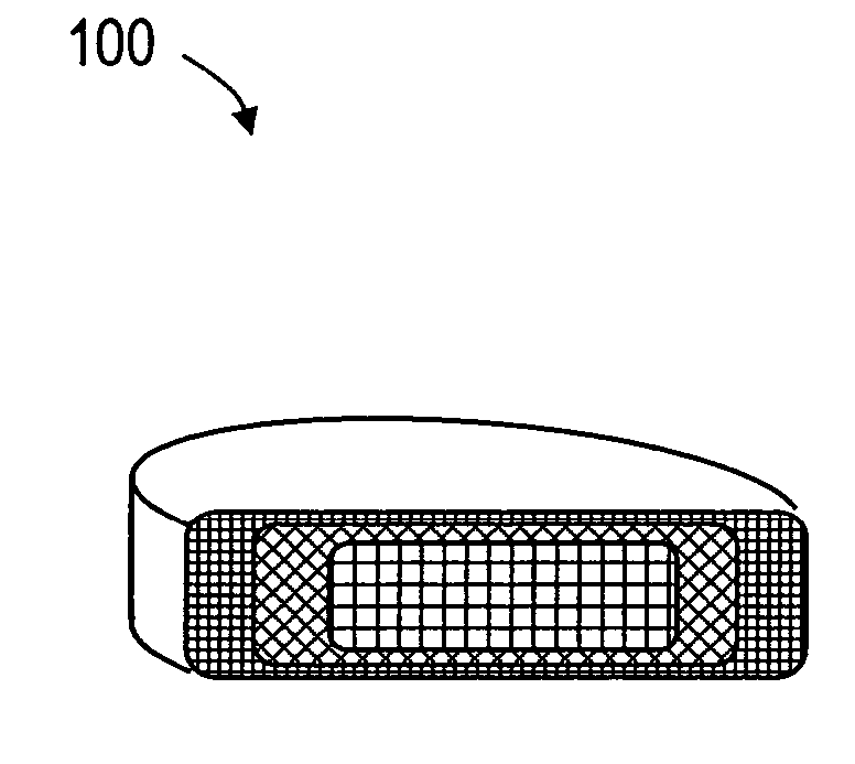
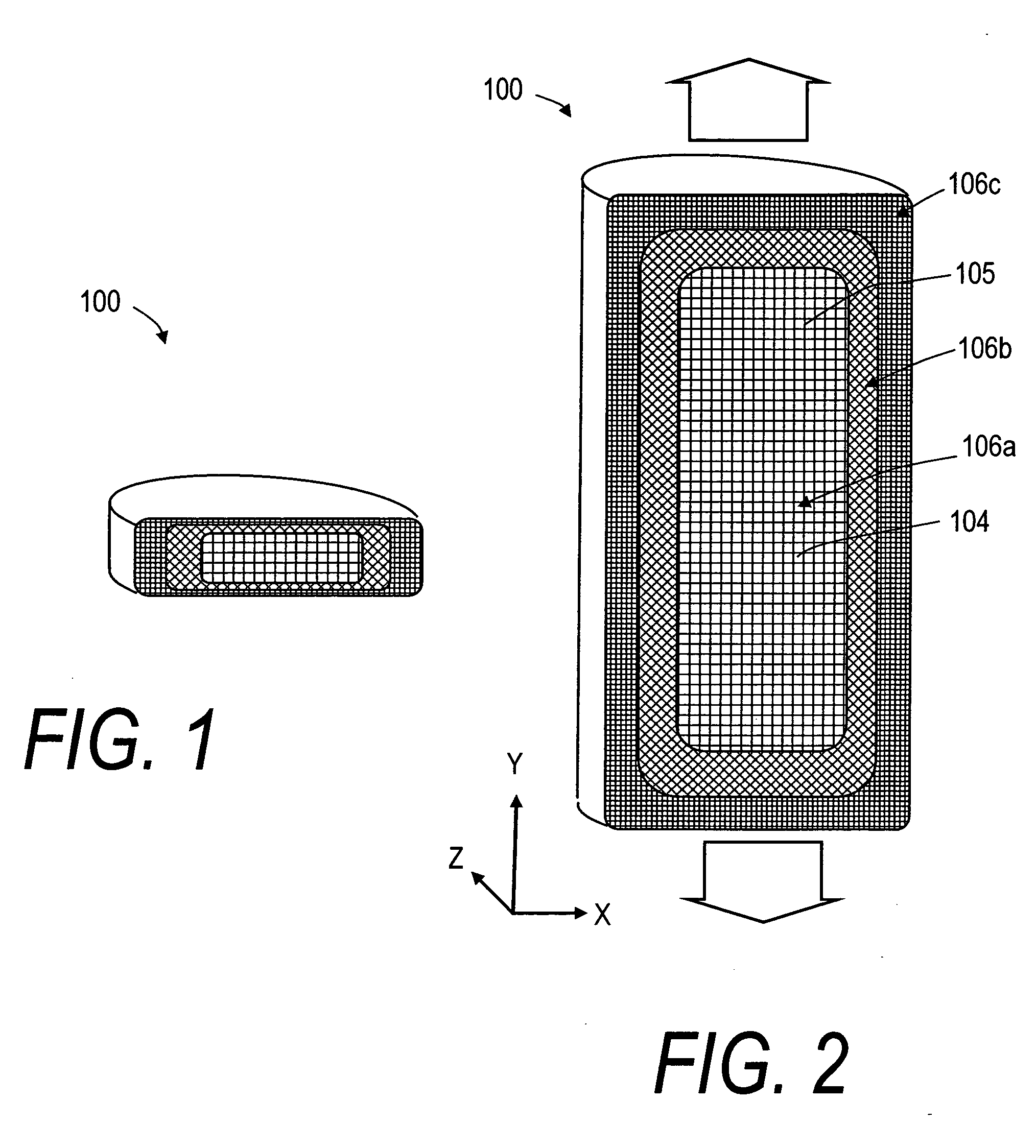
[0033]FIGS. 1 and 2 depict schematic sectional views of an exemplary, deformable flow-through implant body or structure 100 that is configured for treating a fracture in a vertebral body. In FIG. 1, it can be seen that the deformable structure 100 is capable of a collapsed or compacted shape to allow for its introduction into a vertebra through a small diameter sleeve. FIG. 2 illustrates that the deformable structure 100 is capable of extension in a controlled direction relative to x, y and z-axes of the body following the flow of fill material 102 (see FIG. 6) into implant body 100. The fill material 102 can be an in-situ hardenable bone cement, such as a PMMA bone cement that is injected in a common form consisting of (i) a liquid MMA monomer component and (ii) a non-liquid pre-polymerized PMMA bead component. The flow-through structure 100 of FIG. 2 comprises an open web of elements 104 that define flow openings 105 therein. The elements 104 can be filaments or polymer ligaments ...


PUM


Abstract

A system for treating an abnormal vertebral body such as a compression fracture. In an exemplary embodiment, the system includes a biocompatible flow-through implant structure configured with a three-dimensional interior web that defines flow openings therein for cooperating with a two-part hardenable bone cement. The flow-through structure is capable of compacted and extended shapes and in one embodiment provides a gradient in flow openings for controlling flow parameters of a bone cement injected under high pressure into the interior thereof. The flow-through implant structure is configured for transducing cement injection forces into a selected direction for moving apart cortical endplates of a vertebra to reduce a fracture. In one embodiment, the flow-through implant structure is coupled to an Rf source for applying Rf energy to a two-part bone cement to accelerate curing of the cement to thereby allow on-demand alterations of cement viscosity. The Rf system allows for control of bone cement polymerization globally or regionally to prevent cement extravasion and to direct forces applied to a vertebra to reduce a fracture.

Description

CROSS-REFERENCE TO RELATED APPLICATIONS [0001] This application claims benefit of Provisional U.S. Patent Application Ser. No. 60 / 605,700 filed Aug. 30, 2004 titled Vertebral Implant Constructs, Methods of Use and Methods of Fabrication. This application also is related to U.S. application Ser. No. 11 / 165,652 (Atty. Docket No. DFINE.001A1, filed Jun. 24, 2005 titled Bone Treatment Systems and Methods; and U.S. patent application Ser. No. 11 / 165,651 (Atty. Docket No. DFINE.001A2), filed Jun. 24, 2005, titled Bone Treatment Systems and Methods. The entire contents of all of the above cross-referenced applications are hereby incorporated by reference in their entirety and should be considered a part of this specification.BACKGROUND OF THE INVENTION [0002] 1. Field of the Invention [0003] The present invention relates to medical devices, and more particularly, to methods and apparatus for treatment of abnormalities in bone such as osteoporotic bone, bone fractures, avascular necrosis an...

Claims


Application Information

Patent Timeline
Patent Type & Authority Applications(United States)
IPC IPC(8): A61F2/44
CPCA61B17/7095A61B17/7098A61B17/8836
Inventor TRUCKAI, CSABASHADDUCK, JOHN H.
Owner DFINE INC
Why Eureka
Try Eureka