
Synchronous motor control method and synchronous motor control system

a technology of synchronous motors and control methods, applied in the direction of electronic commutators, dynamo-electric converter control, sustainable manufacturing/processing, etc., can solve the problems of excessive current supply to the synchronous motor, high manufacturing cost of the high-speed synchronous motor, and high cost of high-speed synchronous motors. , to achieve the effect of preventing the burning suppressing the heat generation of the synchronous motor, and reducing the intensity of magnetic fields

Active Publication Date: 2006-05-25
KAWASAKI HEAVY IND LTD
View PDF4 Cites 22 Cited by
  • Summary
  • Abstract
  • Description
  • Claims
  • Application Information

AI Technical Summary

Benefits of technology

[0010] Accordingly, it is an object of the present invention to provide a synchronous motor control method and system for controlling a synchronous motor, capable of making the synchronous motor produce high torque at a high rotating speed and of improving the efficiency of the synchronous motor.

Problems solved by technology

The allowable maximum current and allowable maximum voltage of the high-speed synchronous motor are high, the high-speed synchronous motor is inevitably large and the manufacturing cost of the high-speed synchronous motor is high.
Therefore, it is very probable that an excessively high current is supplied to the synchronous motor.
Consequently, the improvement of the efficiency of the synchronous motor is obstructed, the synchronous motor generates heat at a high rate and the power factor decreases.

Method used


Image

  • Synchronous motor control method and synchronous motor control system
  • Synchronous motor control method and synchronous motor control system
  • Synchronous motor control method and synchronous motor control system

Examples


first embodiment

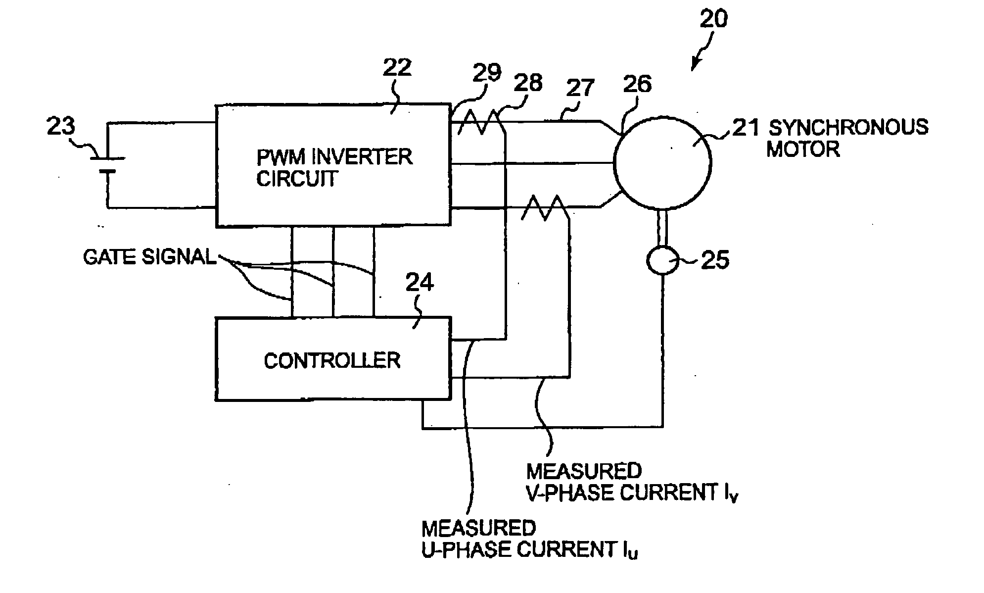
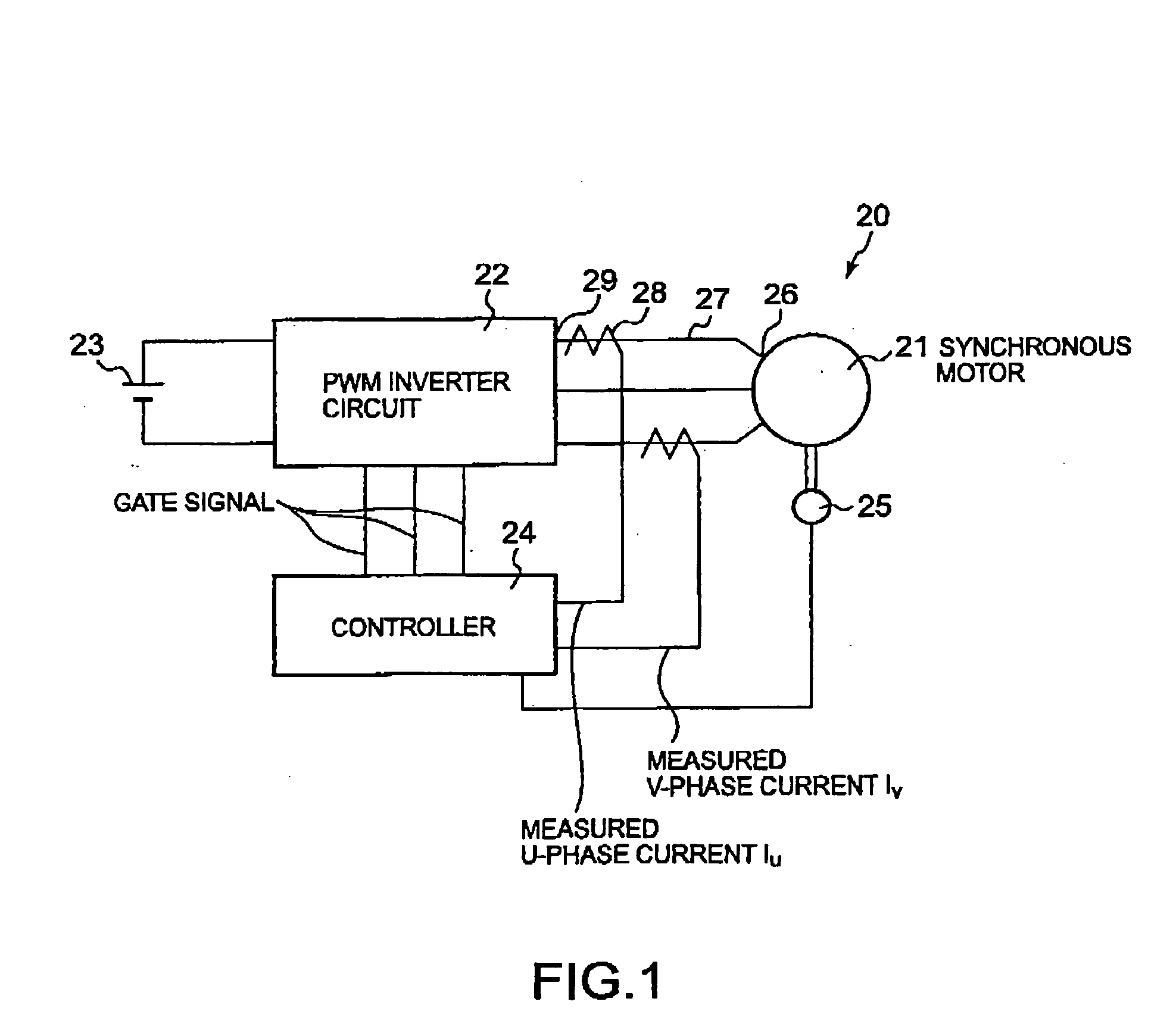
[0042] Referring to FIG. 1 showing a synchronous motor control system 20 in a first embodiment according to the present invention, the synchronous motor control system 20 includes a synchronous motor 21, a PWM inverter circuit 22, a dc power supply 23 and a controller 24. The synchronous motor 21 is a three-phase synchronous motor, such as a cylindrical brushless dc motor.

[0043] The inverter circuit 22 converts dc power provided by the dc power supply 23 into three-phase ac power and supplies the three-phase ac power to the synchronous motor 21. The inverter circuit 22 is provided with a plurality of switching devices for supplying ac currents to the three phases of the synchronous motor 21. The inverter circuit 22 has three output terminals 29 connected to three terminals 26 connected to the three phases of the synchronous motor 21 by connecting lines 27, respectively.

[0044] The controller 24 gives gate signals to the switching devices to make the inverter circuit 22 deliver sinus...

second embodiment

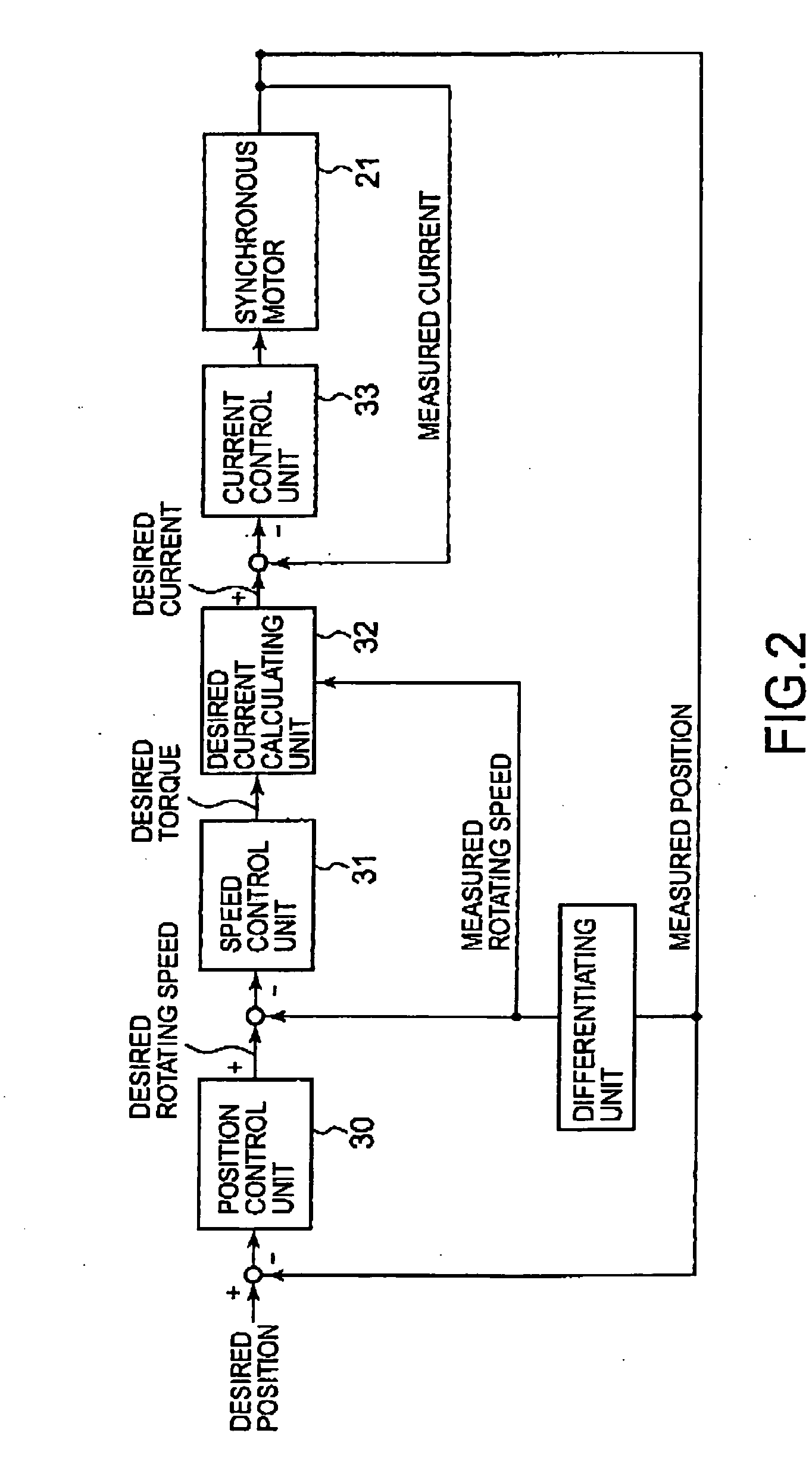
[0081] The desired current calculating unit 132 uses a given desired torque as a first desired q-axis current Iqc1. Basically, the synchronous motor control system in the second embodiment calculates a desired d-axis current Idc by using Expression (8) and uses a first desired q-axis current Iqc1 and a first desired d-axis current Idc1 as a desired q-axis current Iqc and a desired d-axis current Idc.

[0082] A d-axis current Id exceeding a maximum field-weakening current having a maximum effect on weakening a magnetic flux φa in a synchronous motor 21 does not have a field-weakening effect higher than that of the maximum field-weakening current. Therefore, if a desired first d-axis current Idc1 calculated by using Expression (8) is higher than the maximum field-weakening current Idmax, the maximum field-weakening current Idmax is used as a desired d-axis current Idc.

[0083] If a current |I|, namely, the absolute value of a current I flowing through the synchronous motor 21 is higher t...


PUM


Abstract

A desired q-axis current is determined based on a desired torque, and a desired d-axis current is determined based on the rotating speed of a synchronous motor when the terminal voltage of the synchronous motor coincides with a predetermined maximum permissible voltage to weaken a magnetic field created by the synchronous motor equivalently and to prevent the drop of the output torque of the synchronous motor. The desired d-axis current is determined based on the desired torque and the rotating speed. Therefore, the desired d-axis current can be reduced when a high torque is not necessary and undesired increase of the desired d-axis current can be prevented. Thus the synchronous motor operates efficiently, heat generation of the synchronous motor is prevented and power factor is improved.

Description

CROSS REFERENCE TO RELATED APPLICATIONS [0001] This application is based upon the prior Japanese Patent Application No. 2004-340505 filed on Nov. 25, 2004, the entire contents of which are incorporated herein by reference. BACKGROUND OF THE INVENTION [0002] 1. Field of the Invention [0003] The present invention relates to a synchronous motor control method and a synchronous motor control system. [0004] 2. Description of the Related Art [0005] In a synchronous motor, induced voltage produced by speed electromotive force increases with the increase of the rotating speed of the rotor of the synchronous motor. The polarity of the induced voltage is opposite that of the output inverter voltage of an inverter circuit. Therefore, increase in the induced voltage causes the output torque of the synchronous motor to decrease. If the voltage across the terminals of the synchronous motor drops instantly, the output torque of the synchronous motor decreases furthermore. [0006] Therefore, when hi...

Claims


Application Information

Patent Timeline
IPC IPC(8): H02P1/46H02P6/06H02P6/08H02P6/17H02P6/28H02P21/00H02P21/22H02P23/12H02P23/16H02P25/022H02P27/04
CPCH02P21/0035H02P25/021H02P21/22H02P25/024Y02P80/10
Inventor TANAKA, HIDEKIKAJIHARA, SHINJIMAEHARA, TSUYOSHIKUBOTA, TETSUYA
Owner KAWASAKI HEAVY IND LTD
Learn More