Method and apparatus for reducing frequency errors associated with an inter-system scan

a technology of inter-system scan and frequency error, which is applied in the direction of polarisation/directional diversity, wireless communication, and assessment restriction, etc., can solve the problems of adding additional cost and complexity to the circuit, wcdma system and gsm system synchronization is not common, and the overhead of circuit complexity is small, memory space and energy consumption is reduced, and errors already have been substantially reduced

Inactive Publication Date: 2006-05-25
QUALCOMM INC
View PDF7 Cites 19 Cited by
  • Summary
  • Abstract
  • Description
  • Claims
  • Application Information

AI Technical Summary

Benefits of technology

[0027] As will be appreciated from the following description of a receiver in which the invention is embodied, if the reference oscillator is allowed temporarily to achieve phase lock with the new system and just receive the samples as normal, i.e. allow the reference oscillator to become phase locked before starting the received data sampling, then the received samples will have the correct phase and no post correction will be required. This approach requires very little overheads in circuit complexity, memory space and energy consumption.
[0028] Furthermore, the problem of maintaining phase lock with the continuous frequency division duplex (e.g. WCDMA) system while temporarily achieving phase lock with the GSM system is overcome or at least mitigated by estimating the error induced by retuning to the time division duplex (e.g. GSM) system in order to apply a correction for it before the WCDMA system is re-acquired. The correction can be computed before (or during) the inter-system scan and applied during the receiver reconfiguration period, so that when the WCDMA system is re-acquired, the error will already have been substantially reduced.

Problems solved by technology

While it would be possible to do this from within the system, such an approach would place an undue burden on the system because it would have to monitor both active and idle mobile units.
Furthermore, there is no common synchronization between a WCDMA system and a GSM system.
A problem with this approach is that a hardware rotator requires additional hardware, and hence uses extra silicon area, and therefore adds additional cost and complexity to the circuit (which is usually provided in the form of an ASIC).
A problem with this approach is that a signal processing rotation algorithm such as this requires code to be written, memory in which to store it and a DSP (digital signal processor) powerful enough to run it in the required time.
This approach therefore consumes DSP memory and energy from the battery.
This retuning results in a frequency error being introduced into the synchronization of the phone to the WCDMA system, making the re-acquisition more difficult when returning to the WCDMA channel.
However, this approach is not entirely satisfactory at least for the following reason.
This fine-tuning results in a frequency error being introduced into the synchronization when the phone is reconfigured to return to the WCDMA system in the above action 5.
Consequently, the re-acquisition in action 6 is more difficult to perform.

Method used


Image

  • Method and apparatus for reducing frequency errors associated with an inter-system scan
  • Method and apparatus for reducing frequency errors associated with an inter-system scan
  • Method and apparatus for reducing frequency errors associated with an inter-system scan

Examples


Embodiment Construction

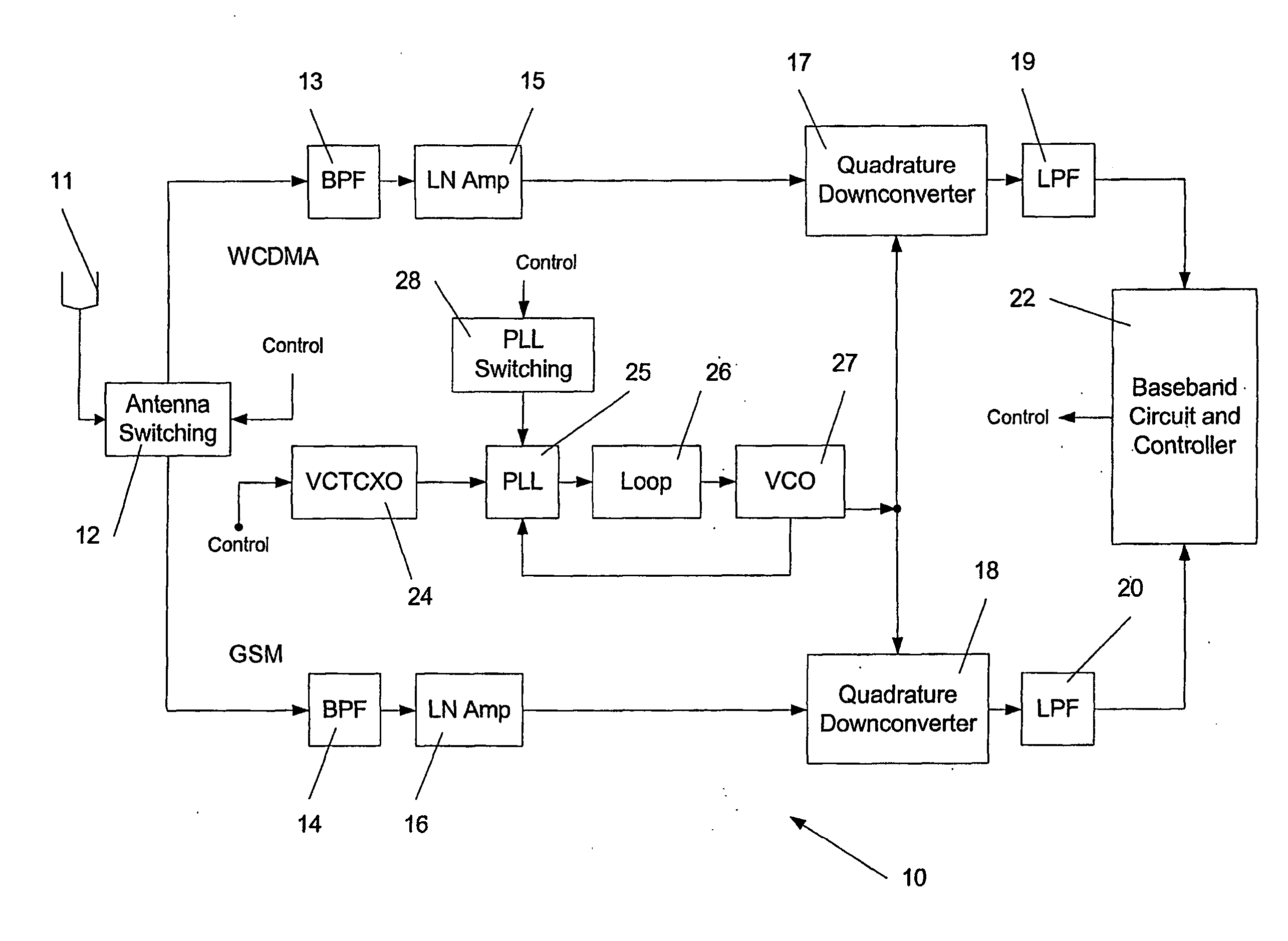
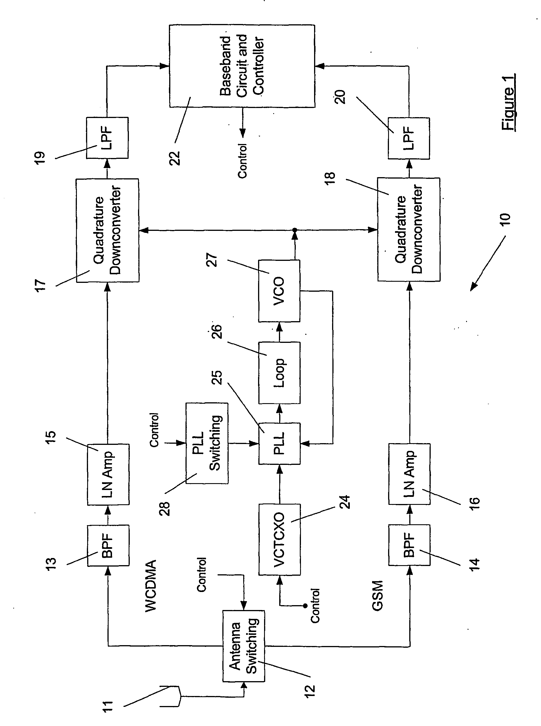
[0036]FIG. 1 is a schematic circuit diagram representing a dual mode receiver 10 for a mobile unit. For the purpose of explanation the dual mode receiver 10 is illustrated as being capable of receiving either WCDMA or GSM signals. It will be appreciated that other combinations of receivable signals are possible. Signals received at an antenna 11 are switched by a switching component 12 to either a WCDMA receiver chain (shown in the upper part of FIG. 1) or a GSM receiver chain (shown in the lower part of FIG. 1). Both receiver chains operate in essentially the same way insofar as the received signal is: filtered by a bandpass filter (BPF) 13,14; amplified by a low noise amplifier 15,16; down-converted to a baseband frequency by a down-converter 17,18; and filtered by a lowpass filter 19,20 before being input to a baseband circuit and controller 22 for further processing.

[0037] The receiver 10 also comprises a voltage controlled temperature compensated crystal oscillator (VCTCXO) 24...


PUM


Abstract

A plural-mode receiver 10 is able to receive signals from a first communication system (e.g. WCDMA) or signals from a second, different communication system e.g. GSM). The receiver 10 comprises a first receiver chain 13, 15,17,19 for receiving signals of the first communication system and a second receiver chain 12, 14, 16, 18 for receiving signals of the second communication system. A reference oscillator 24 is arranged to generate a reference signal for the first receiver chain and the second receiver chain. The receiver also comprises a controller 22 for controlling the reference oscillator 24 so that the oscillator 24 oscillates at frequencies related to signals of the first communication system or signals of the second communication system. The controller 22 records the change in frequency of the oscillator 24 resulting from changing to the frequencies related to signals of the second communication system and a period of time during which signals of the second communication system are received by the second receiver chain. The controller 22 then calculates from the recorded change and the recorded period of time an error vector and changes parameters of the reference oscillator 24, including applying the calculated error vector, so that the oscillator oscillates at frequencies related to signals of the first communication system.

Description

BACKGROUND OF THE INVENTION [0001] I. Field of the Invention [0002] The invention relates generally to a method of and apparatus for reducing frequency errors associated with an inter-system scan. The invention is useful for reducing frequency error when performing an intersystem scan between a continuous frequency division duplex system, for example a WCDMA system, and a differently duplexed system, for example a time division duplex system such as GSM, but is not limited to such an application. [0003] II. Description of the Related Art [0004] In the following, reference will be made to the WCDMA and GSM standards, but it will be appreciated by those possessed of the relevant skills that the invention is not limited to those standards and may be applied to inter-system scans between other different communication systems. The terms “mobile unit” and “mobile phone” are also used and, of course, cover mobile phones, but also cover other devices capable of communicating with a cellular...

Claims


Application Information

Patent Timeline
Patent Type & Authority Applications(United States)
IPC IPC(8): H04B7/00H03L7/085H03L7/095H03L7/107H03L7/18H04B1/16
CPCH03L7/085H03L7/095H03L7/107H03L7/18H04B1/16H03L7/1077H04W48/18H04W88/06
Inventor SMITH, ALAN ANDREWSTUART, JULIE
Owner QUALCOMM INC
Why Eureka
Try Eureka